Home › Forums › The Main Forum Area › Projects › Trusty Steed engine rebuild
- This topic has 63 replies, 9 voices, and was last updated 8 years, 8 months ago by
 trusty220.
-
AuthorPosts
-
November 20, 2014 at 9:29 pm #10771
 trusty220Keymaster
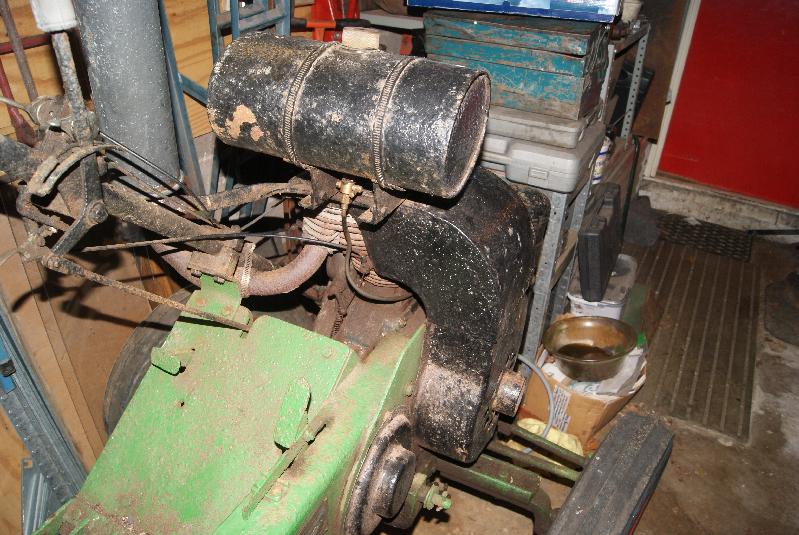
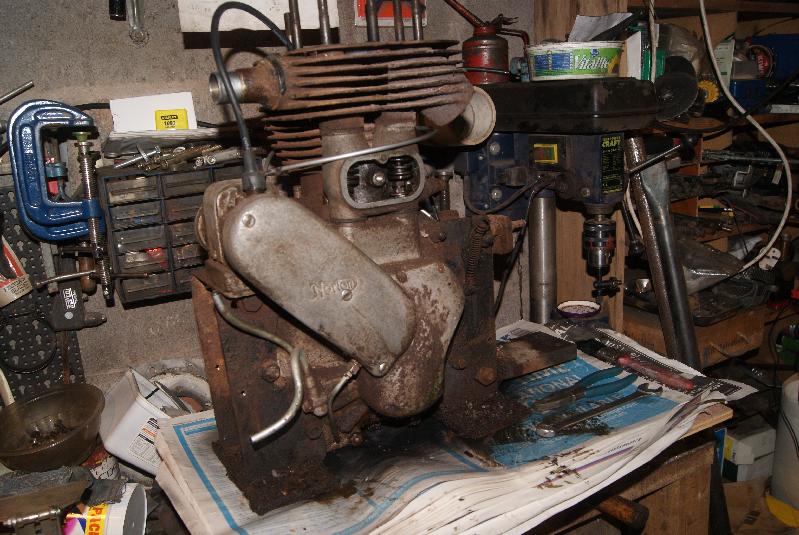
A good friend of mine who lives in Pembrokeshire has been struggling with this engine for some years now, so I suggested that it had a holiday in Redditch this Winter so that I could sprinkle a bit of TLC on it.
As you can see, it is an older restoration but the tractor is basically sound and in working order apart from the engine. The owner suspects a weak spark and a rusty fuel tank, so these will receive special attention whilst being rebuilt.
The rest of the engine will be stripped down and inspected first, then re-assembled and any faults corrected with a view to returning the Steed to it’s owner next Easter ready for the showing season.
(Big breath) Here goes………Attachments:
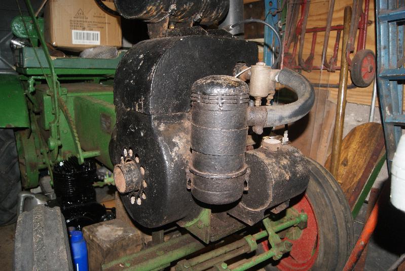
November 20, 2014 at 9:56 pm #10776trusty220KeymasterFirst bits to come off are the fuel tank, supports, cowling and cylinder head. The engine on this Steed is the Norton Big Four which is a single cylinder 600cc four stroke with a dry sump.
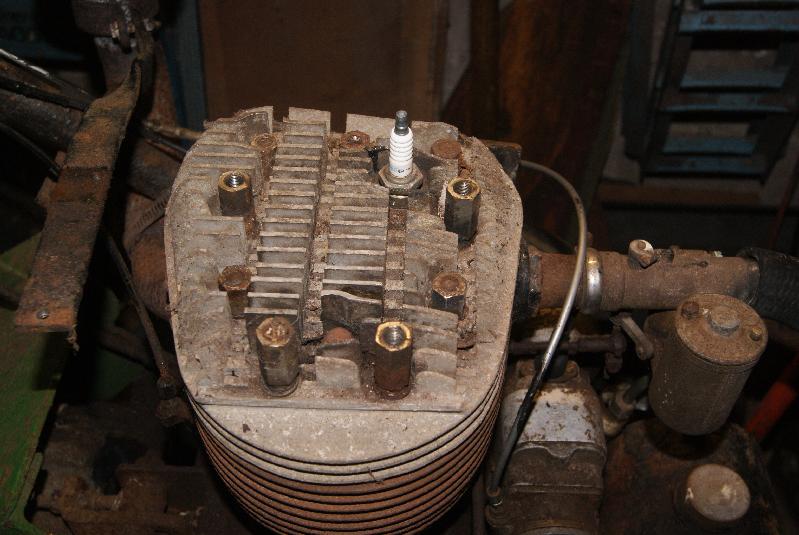
Non standard parts so far are the tank straps (someone has used large jubilee clips) and the home-made exhaust silencer and support. These will have to be sorted at the rebuild stage.An unusual feature of this engine is the way that the cooling fins on the cylinder head have been machined to provide a flat top surface for the cowling; because some of the fin area has been reduced, the factory has machined grooves across the head to increase the surface area.
Attachments:
November 22, 2014 at 10:46 am #10790 will-haggleParticipant
If you (or any other) member needs a Norton Big 4 (600cc sidevalve) manual, I can email a pdf from the Norton factory manual.
November 22, 2014 at 5:37 pm #10794trusty220KeymasterThanks for that, Alan; I do have a workshop manual for this engine, but many of our members would appreciate it I’m sure.
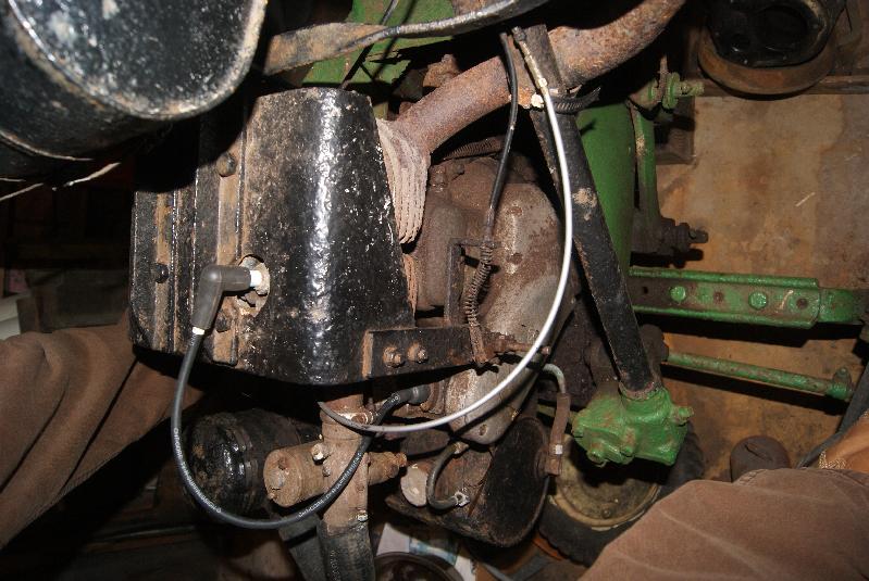
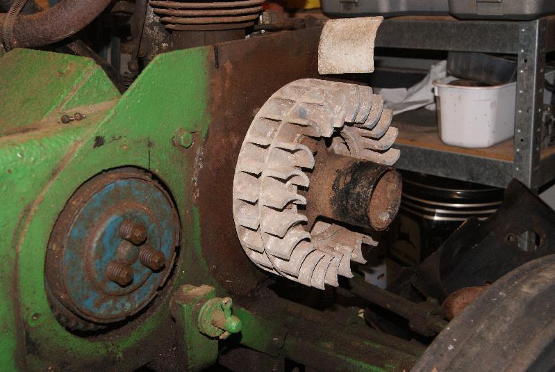
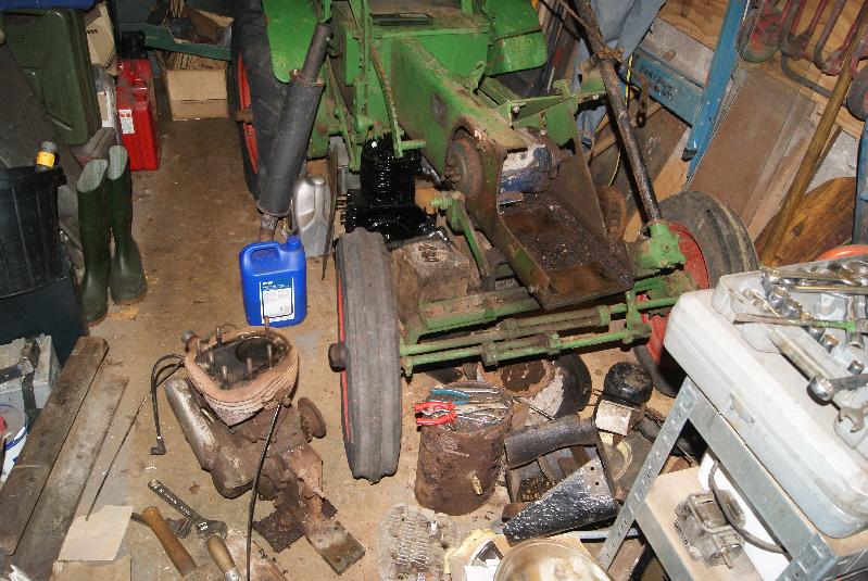
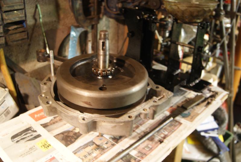
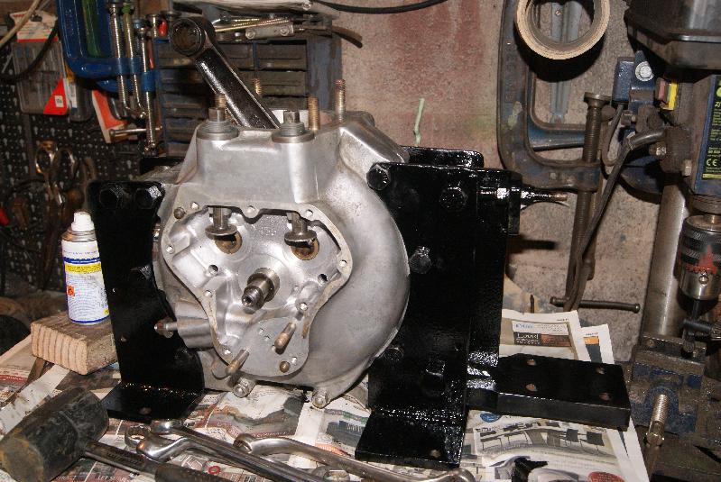
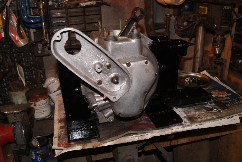
I will get down to some more dismantling on Sunday and (hopefully) uncover the engine number.November 23, 2014 at 6:58 pm #10804trusty220KeymasterI’d forgotten what a job it is to remove the engine on these beasties. As you can see from the pictures the fan housing has to come off, followed by the fans and the fan carrier so that the crankshaft will fit through the side plate.
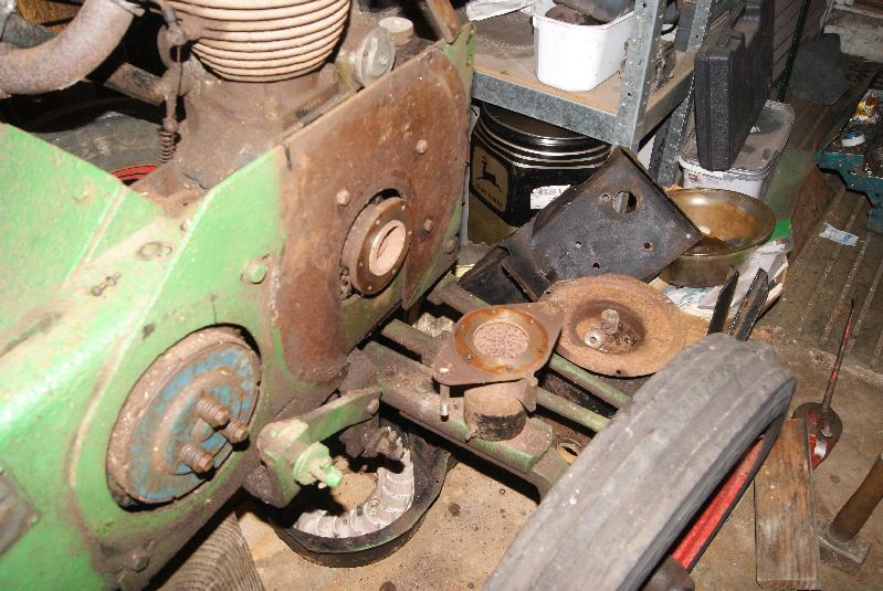
Ideally it would be great to slide the engine and gearbox as one assembly out of the front of the chassis, but that won’t happen unless you take the clutch assembly off. I opted for the easy way out and took the gearbox off it’s mounting plate so that the engine will come out by itself with all of the mountings in place.
You can see where the gearbox fits from the one photo- it goes on the flat plate at the rear of the engine, and you can tension the engine>gearbox chain by pivoting the carrier downwards using the jacking post at the top.
See if you can spot the section of railway line that I use as an anvil. It fell over this afternoon and dug a hole in my ankle, making me swear and starting the wife nagging me to go to A&E! Typical bloke’s cure- sit in front of telly with a glass of something strong that will knock me out when I go to bed.
Tomorrow’s another day!Attachments:
November 23, 2014 at 7:42 pm #10809trusty220KeymasterI forgot to pick the right photo. I think the booze is kicking in!
Attachments:
November 30, 2014 at 4:58 pm #10861trusty220KeymasterSorry for the delay, but here’s the next stage. I don’t think this engine has ever been apart and it’s been fighting me all the way, making me use all the cunning tricks that I’ve learnt over the years messing with all sorts of machinery.
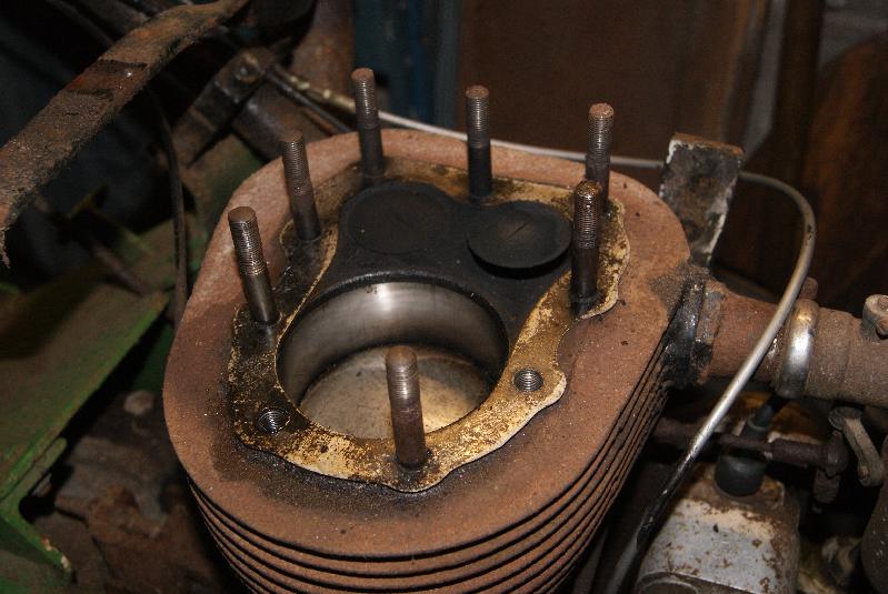
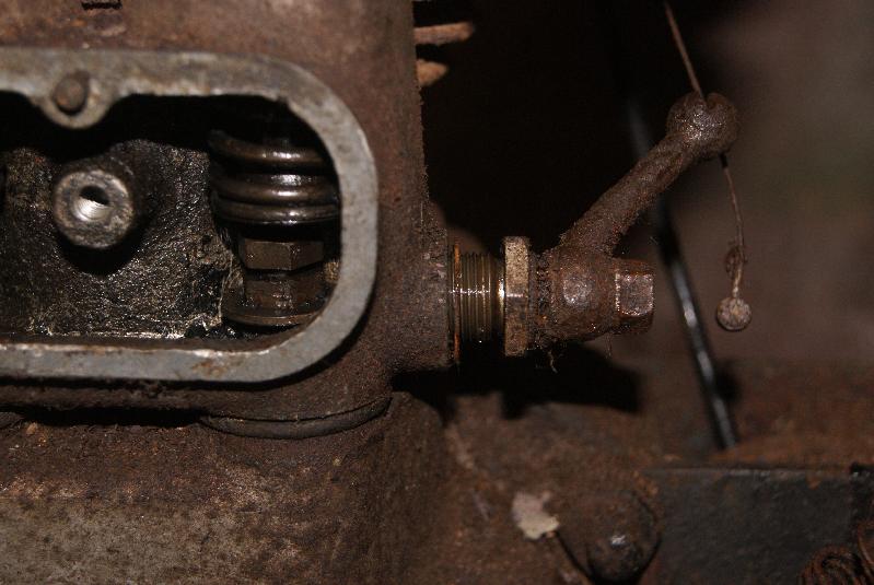
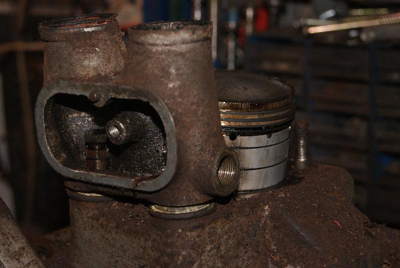
First item to remove is the cylinder barrel. On the Steed the engine is more like the motorbike engine with a separate aluminium valve chest- on the 2-wheeler the valve chest is cast into the cylinder casting- and there is a valve lifter incorporated into the valve chest alongside the exhaust valve. The easiest way to dismantle it all is to unscrew the valve lifter as an assembly so that it doesn’t foul anything as you lift the barrel off. The valve chest won’t come off until you undo the exhaust tappet adjuster and remove the washer underneath- this is what the valve lifter pushes up. Once the washer is off the casting will then pass over the cam followers.
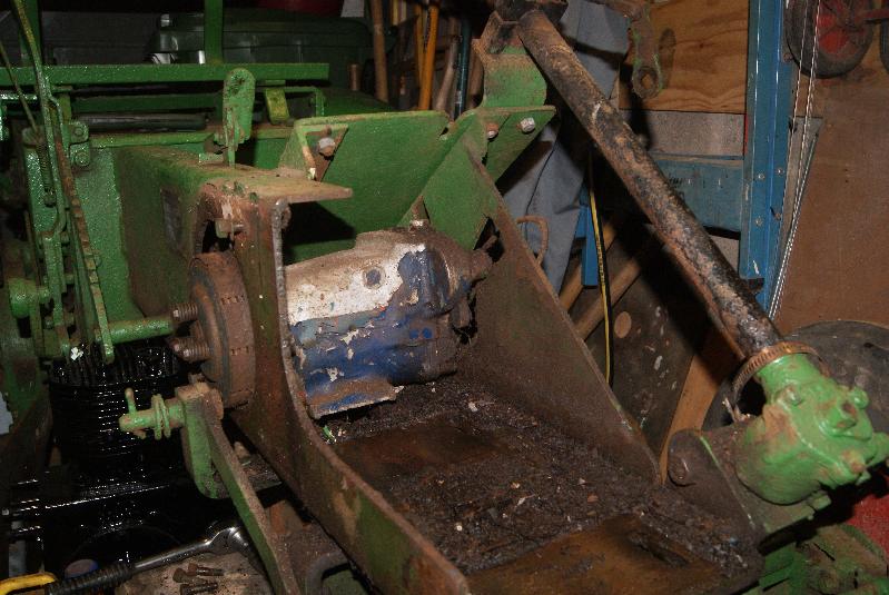
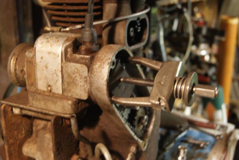
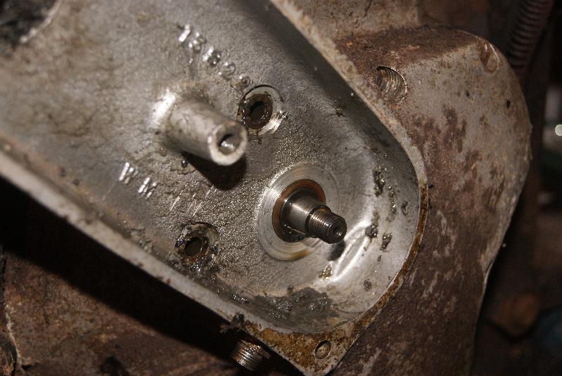
Now the one everyone hates- the magneto! It is very simple to remove in the book, but then the people who write the books very rarely have to do the job! Remove the three screws from the timing chain cover and remove the cover. You can now see the two sprockets with an endless chain between them. Don’t bother looking for a joining link because there isn’t one, the chain is fitted when the sprockets are put on. Starting with the magneto sprocket, undo the nut holding it on (it is a normal right-hand thread, so it ondoes anticlockwise). The sprocket will still not come off because it will be locked on a taper. At this stage do not be tempted to put a lever behind it because you will only damage the magneto internally; the correct way to remove the sprocket is to use a small puller. You can see the idea in the photo, with the legs pulling the sprocket and the centre screw pushing back on the armature spindle; to protect the threads on the spindle I have refitted the nut loosely until it is flush with the end of the thread, then put a steel plate over the spindle to take the bruising from the screw. Tighten the screw, apply a little heat as necessary to the sprocket and it should pop off. Try to avoid hitting the end with a hammer because you may damage the bearings in the mag.
All that you need to do now is to undo the bolt that is holding the magneto platform to the engine mount and the magneto can be taken off. Beware that it does look like there are two bolts holding it on, but the one closest to the engine is passing through the crankcase and not the magneto platform.Attachments:
November 30, 2014 at 5:11 pm #10865trusty220KeymasterNow we have to get into the timing gears, so the first bit is to use the puller again to take off the second sprocket on the timing chain. Same procedure as before, normal right-hand thread on the nut and then the sprocket is on another of those tapers. If this one won’t budge you can give it a tap with a hammer, but not too hard otherwise you may damage the thread.
Once that is off, undo the ring of screws around the outside (mine were all seized solid) and the two in the timing case and the cover should lift off. Beware that there is a little brass thimble with a spring behind it on the outlet of the oil pump that is easy to drop on the floor and lose; make sure that you put it somewhere safe straightaway!
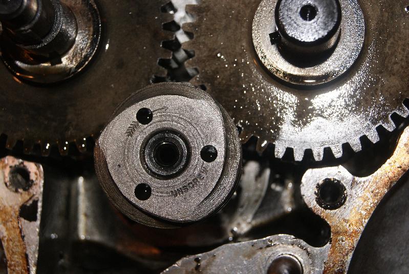
The oil pump is simply detached by undoing the two nuts holding it on; the scroll that drives the oil pump is a left hand thread, and if you wipe off the surface you will see a little arrow and the word “unscrew”. Turn clockwise to undo it and remove it- I used a small brass centre punch to get it moving so that it wouldn’t hurt the metal- then lift off the gears with their cams attached. That only leaves the centre drive gear which is keyed to the crankshaft- again, use the puller and remove this.
Next thrilling instalment soon!Attachments:
December 7, 2014 at 5:32 pm #10983trusty220KeymasterJust a quick update to say that I have now taken the two halves of the crankcase apart and de-greased them, but unfortunately no photo’s to show.
I’ve had a bit of a break from it this week because someone tried to break in to the workshop at work on Saturday and I’ve spent most of my weekend trying to secure it again- one of the joys of being a manager and a keyholder, I suppose.
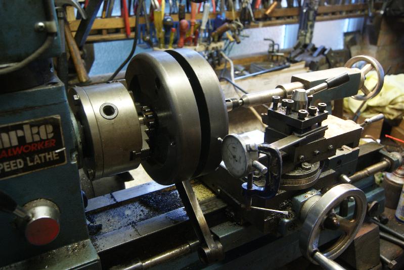
Business as usual next week, all being well!December 22, 2014 at 8:48 pm #11156trusty220KeymasterWith the crankshaft out of the engine I felt it wouldn’t hurt to put a dial gauge on the crankshaft to make sure it is true. Not such a silly statement, because the crank is made in five separate parts which are bolted and clamped together; the main items are the crank webs which are also the flywheels, and these are held together by the big-end crankpin. This crankpin has a male thread on each end which projects through each flywheel, then a large nut on the outside is tightened to hold it all together. The only trouble is there is no keyway in either end of the crankpin, so the flywheels are free to move as the nuts are tightened. The only way to adjust them is to loosen the nut on one side and knock the flywheel half with a large piece of wood until the flywheels run true to each other. It is impossible to get them exactly lined up, but a run-out of 5 thou is acceptable.
With the main bearing stubs located, the easy way to do it is shown in the pictures. You need to hold the two ends of the crank and rotate it slowly by hand whilst holding a dial gauge against one side, then adjust and repeat for the other side. If you don’t have a handy lathe you can always use a pair of V-blocks.Attachments:
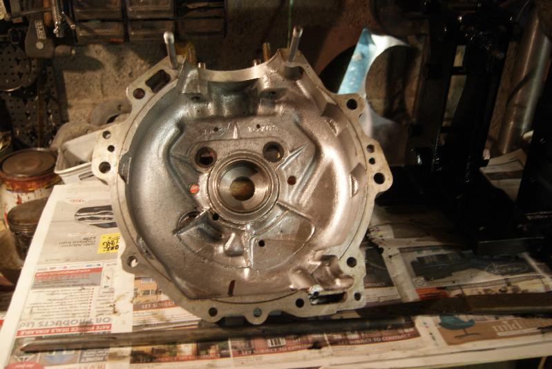
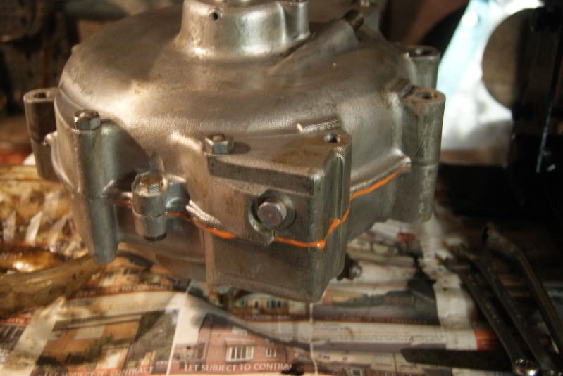
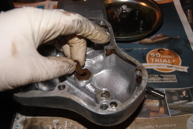
December 22, 2014 at 9:02 pm #11159trusty220KeymasterWell, that checked out OK so the next bit is to put it back in the engine. As you probably realise now, this is not a normal engine; it originally started life in the 1920’s as a motorbike engine which is why it has a circular crankcase and internal flywheels. It also has a dry sump, which means that the oil is pumped out of the crankcase into a separate tank to cool, then pumped back into the engine. The pump that sucks it out of the engine has a pick-up pipe at the front of the engine in the small square reservoir that you can see in the photo’s. It has a screw holding the outer part of it together, and this must have a fibre washer under the head otherwise the oil will track down the screw and make a mess on the floor.
Another part of re-assembly is checking the end float of the crankshaft. There is no easy way of doing this other than putting it all together and trying to move the crank in and out, then taking it apart to put shims under the bearings and trying it all over again. Very time consuming but very necessary, and you shouldn’t skimp on this stage.
Once you’ve done this to your satisfaction you can bolt the engine mountings back on to stabilise the whole assembly and give yourself a pat on the back!Attachments:
December 29, 2014 at 5:25 pm #11248trusty220KeymasterThat’s it, Christmas over and back to work in the garage. It’s freezing, so best to work on the engine rather than respray the Trusty trailer because the paint will never dry at this temperature.
Well, then, where did I get to? Camshafts, timing gears and oil pump next, I think. It sounds simple but beware, it’s very easy to get it expensively wrong.
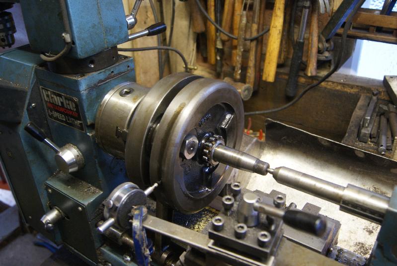
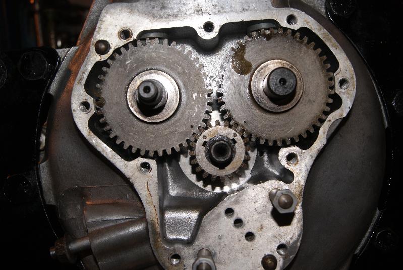
First on the crankshaft is the timing gear; the gear itself has three keyways and two dots for timing marks, so here’s what you do:
Set the crankshaft to TDC- this will put the keyway and key in the crankshaft at the 6 o’clock position;
with the dots on the timing gear facing away from the engine (i.e.pointing towards you), put the dots at the 10 o’clock and 2 o’clock positions;
there should be a keyway at the bottom of the gear that lines up with the key in the crank, so push it on until it stops hard against the shoulder on the crank;
starting with the inlet camshaft (that’s the one with the thread on the end of it), lift the cam follower and position the cam so the dots on timing gear and cam line up, then slide it all the way home into it’s bearing bush;
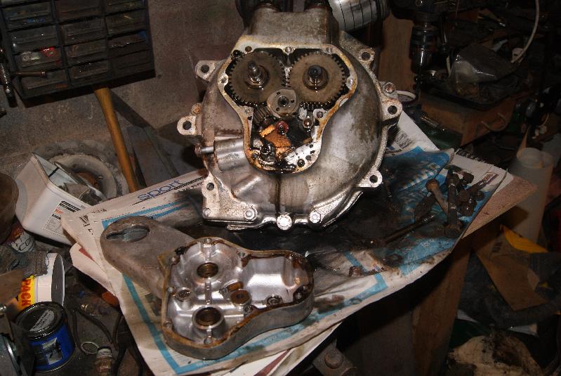
repeat for the exhaust cam and you should end up with something like the photo below, with both cams fitted and all the dots lining up.
If you want to do the test and rotate the engine to make sure the valve timings are right then go ahead- the easiest way is to position the crank on TDC again, only this time between the exhaust stroke and the inlet one; you should see the exhaust closing as the inlet opens (this is called “on the rock”).
Assuming everything is OK, go ahead and fit the worm drive for the oil pump, but beware that it is a left-handed thread so you tighten it anticlockwise. make sure that you do this up tightly because it also retains the timing gear on the crankshaft.Attachments:
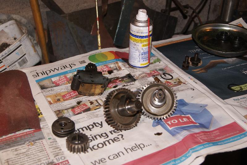
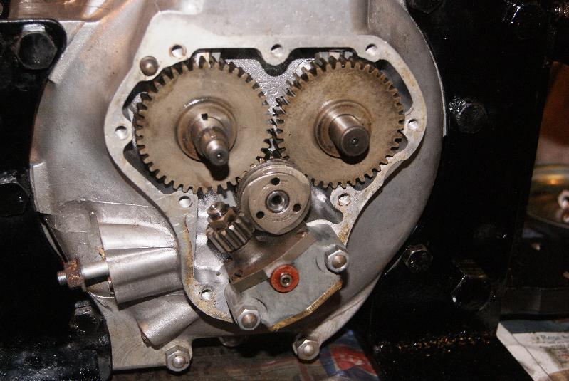
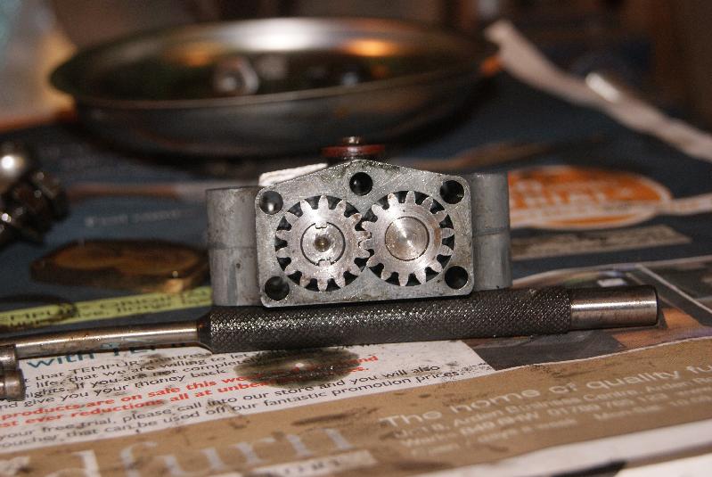
December 29, 2014 at 5:51 pm #11251trusty220KeymasterAll of this work would be wasted if we didn’t check the oil pump over for faults. This engine is quite sophisticated for it’s time in having a force-fed lubrication rather than the splash type that is still in current use today; splash lubrication is exactly what it sounds like- a splasher will throw oil all around the inside of the engine and some of it will actually do what it’s supposed to do. It’s cheap, and that’s why it is still used. Norton have done the job properly, however, in that oil is force-fed from a pump through the end of the crank to the big-end; it is then allowed to circulate inside the engine until gravity makes it fall down to a small sump from where it is sucked out and returned to the external oil tank. Most racing engines and aero-engines use an identical system because it allows for proper cooling of the oil before it passes through the engine again.
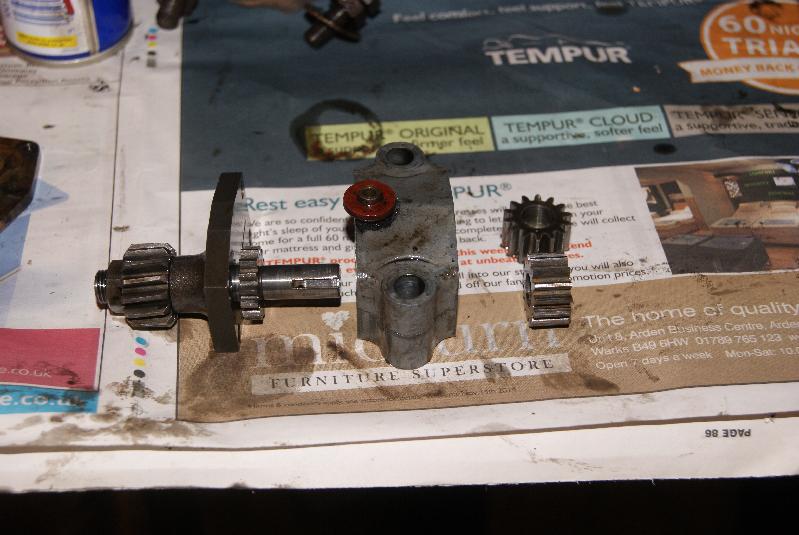
Norton have taken it to another stage in that they have made the two pumps in one- the scavenge side that sucks the oil out of the engine is twice as big as the inlet side, and you can see this from the photo’s. The idea is that if the oil gravity-feeds through to the engine whilst the engine is not running then there will be a large pool of oil in the crankcase which needs to be got rid of; because it is being sucked out twice as fast as it is being pumped in, then it is drained quite quickly.
Take the pump apart by removing the four screws on the side where the gear drive goes in. You will find that the bottom brass plate will fall off as soon as the last screw is removed. You can then remove the two gears of the scavenge pump and pull the main drive shaft out of the body to expose the pressure pump at the top.
Inspect the pump as normal, i.e. check end plates for deep scoring and check housings and shafts for play. Assuming everything is good then you can re-assemble and fit to the engine with it’s two nuts; make sure that you fit a fibre washer on the outlet so that it seals against the inside of the timing cover.
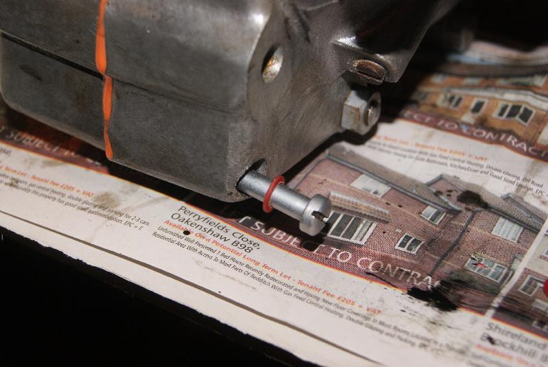
Timing cover is next and this has an oil gallery running inside which has an outlet opposite the end of the crankshaft; so that the two marry up there is a spring-loaded plunger that is fitted to the timing cover- ensure that this is fitted and is free to move in and out, otherwise the crank will not get it’s oil.
Fit the timing cover with gasket sealant and that’s the bottom end of the engine complete- go out for a pint!Attachments:
January 10, 2015 at 3:29 pm #11396trusty220KeymasterThings have been going a little too smoothly lately for my liking, and just when I thought that it was going to be a straightforward job some little gremlin has thrown a spanner in the works.
As you can see, the bottom end of the engine was going along very nicely indeed so I turned my attention to the top end. This is where all the problems seem to be- still, life would be boring if it was all simple, now wouldn’t it?
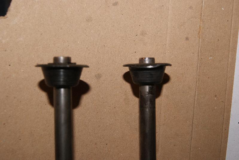
I started off with taking the valves out; quite a bit of persuasion was needed on both valve spring retainers to get the collets to free off, then once the springs, collets and retainers were removed the valves were heavily coated in coke (on the exhaust valve) and the tops of the valves where the collets sit had burred over. Plenty of gentle filing with an oilstone soon de-burred the valve stems, but there still seems to be a problem with the clearance on the exhaust valve guide allowing exhaust gases into the valve chest so a replacement valve guide may be on the shopping list.
After cleaning up the valves didn’t seem too bad but the spring retainers had worn down until they are razor thin, so they will have to be replaced.
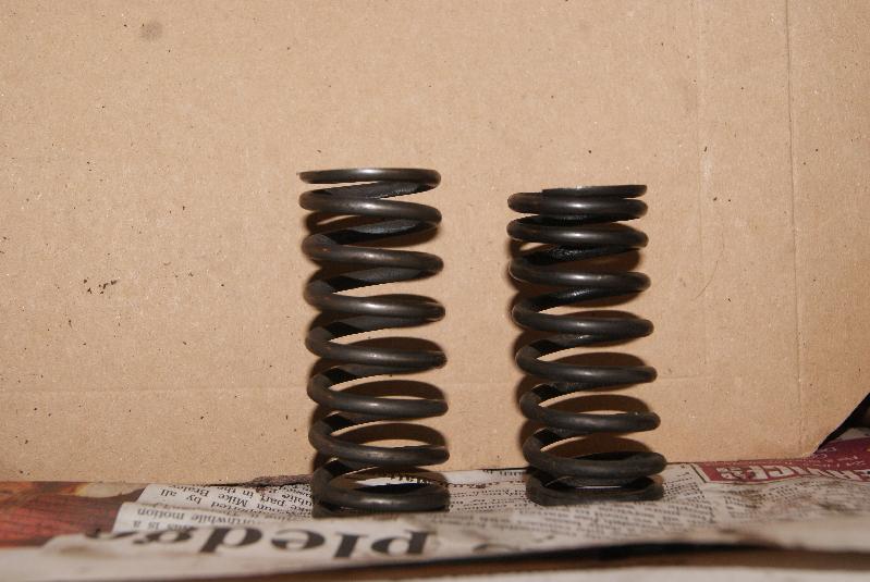
The springs are a different length – they should both be the same- so they will have to be replaced, or the exhaust spring at least.
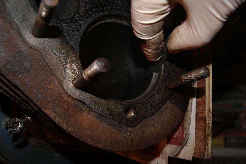
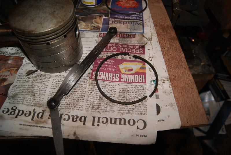
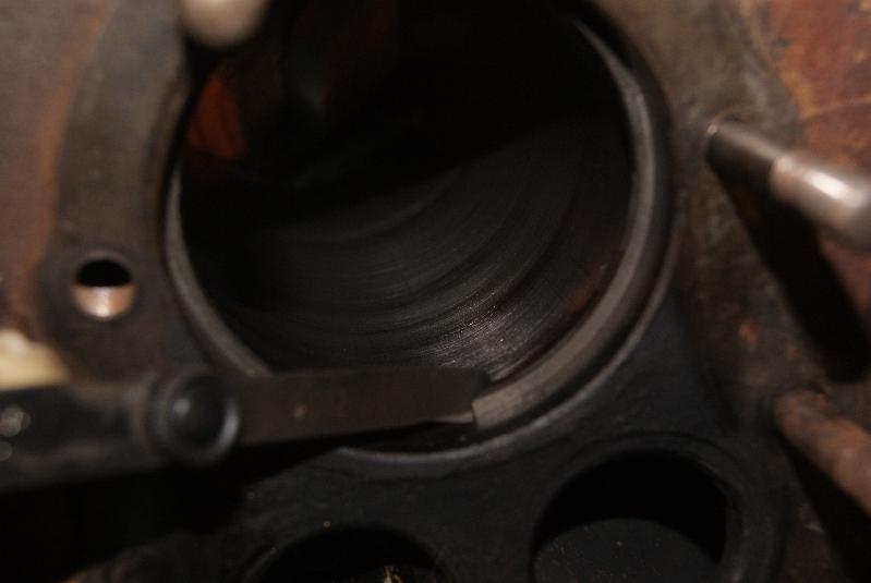
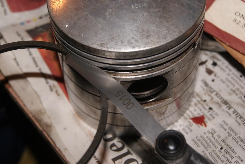
Depressed enough already, I turned my attention to the bore and decided to give it a light honing to get rid of the glaze on the inside. Besides, the coke build up at the top was too great to push the piston into the bore so something had to be done to clean it up. The honing process went off alright, so the next step was to test the end gaps of the piston rings. I got two off with no bother (although I thought they looked a bit thin) but when I got to the last one (the oil control ring) it decided that it wasn’t going to play; it came out of the groove just fine, then as I was sliding it up the piston it broke in two. The only reason that I could think of was that it must have been excessively worn down, so I thought it best to check the other two rings in the bore.
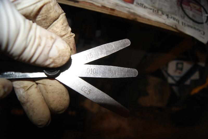
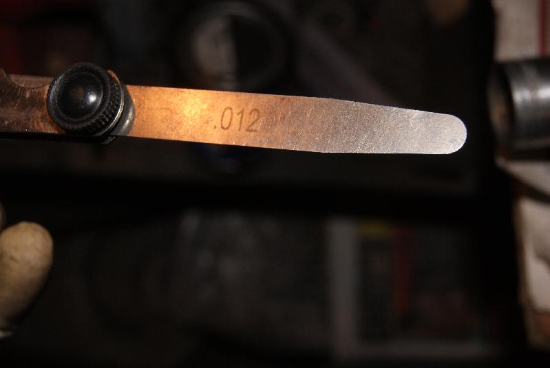
The end gap is what you look for when checking piston rings, and it is usually somewhere around 15 thou. for a normal gap; you have to allow some room for the cast iron to expand as it heats up, but anything over 25 thou. is getting a little sloppy. Both rings measured in at over 50 thou., at least that’s the figure that I stopped measuring at!
So, work is now halted whilst I locate the necessary parts. I’ll try to get away with the inlet valve, valve guide and spring but I will have to replace the exhaust valve guide, exhaust spring and both spring retainers as well as a new set of piston rings and a full gasket set.Attachments:
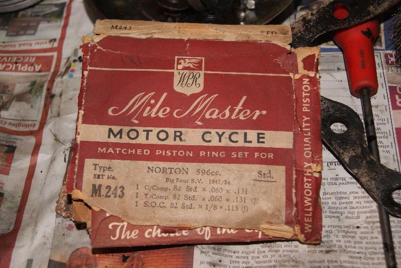
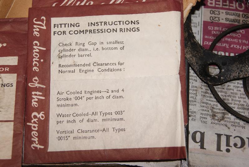
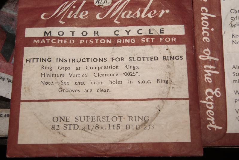
January 21, 2015 at 7:26 pm #11500trusty220KeymasterThings have come to a grinding halt at the minute whilst I try to source parts for this build. First to arrive were the piston rings (£20 from that popular auction site) which were unused old stock from somewhere. Have a look at the packaging- I think it’s great- but more to the point it has instructions on that apply to all engines when rebuilding. Have a read on the photo’s, it’ll save me the trouble of copying it all out!
I’ve checked all of the gaps at top and bottom of the bore and they all come out at around 12-15 thou which is spot-on for this diameter. I also measured the side gap in the grooves on the piston and they were all fine, so next stage is to sort out the valves/springs/retainers and the valve seats.
I’ve just bought a valve re-facing grinder so I can try it out on these valves at the weekend- more in a few days after I’ve picked it up from Cheshire!Attachments:
-
AuthorPosts

- You must be logged in to reply to this topic.