Managed to remove flywheel OK but in the meantime restored the cutter bar to working condition. Tried to attach a photo but didn’t work, never mind. My next question is about the ignition. Have cleaned all components and desoldered the connection between the capacitor (I think they used to call them condensers) and the coil. The capacitor gives what seems to be the correct reading on a DVM but the coil is showing direct to ground. The HT side reads 2.8k Ohms to ground. I presume I need a new coil?
There is a guide to reducing file size for uploading photos in the help and information section of forum at https://vhgmc.co.uk/forums/topic/compressing-photo-files-using-ms-office-picture-manager/
The only way to test a magneto coil thoroughly is with a coil tester, a DVM will give an idea of resistance but will not be able to test insulation for breakdown under running conditions.
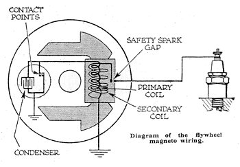
There is a good diagram of magneto circuit on a Villiers website
When replacing the flywheel on a Villiers MK 25C should the flywheel arrow and notch in crankshaft be pointing at the arrow on the magneto backplate or should crank be at TDC with flywheel and casing arrow aligned?
According to the book I have you should first set points gap 0.015″. Then set piston at 5/32″ before TDC, now align mark on flywheel with mark on backplate.
Whenever I time a Villiers engine I set piston to correct position then turn flywheel until points just start to open. I have never used the marks.
The tricky part is getting flywheel tight without disturbing timing.
Thanks Charlie, I did get it running, sort of. Very back firing, at least can’t be miles out. How on earth do you tell where points open? Can’t really see in there. At least I’ve got a good healthy spark with new bits from George.
 .
.