Home › Forums › The Main Forum Area › Projects › Trusty Steed engine rebuild
- This topic has 63 replies, 9 voices, and was last updated 8 years, 8 months ago by
 trusty220.
-
AuthorPosts
-
June 27, 2015 at 2:02 pm #13578
 trusty220Keymaster
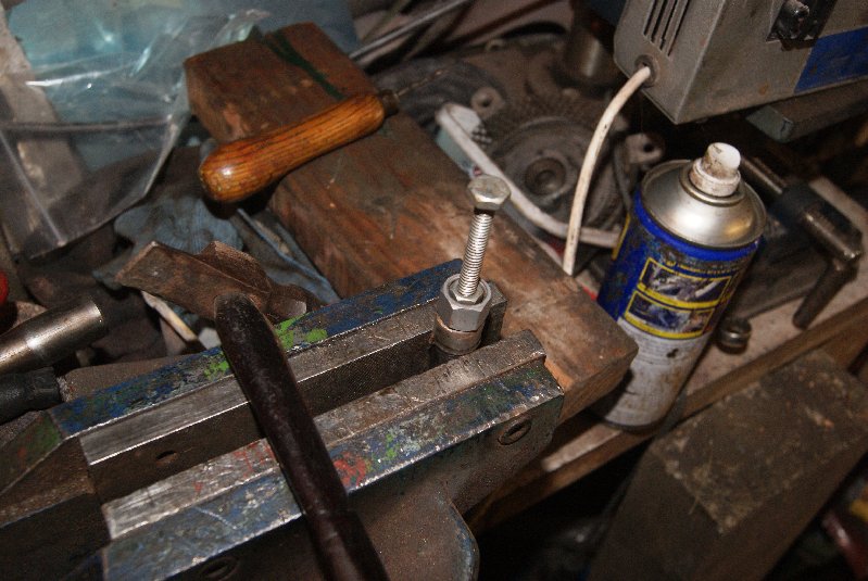
I’m having fun today re-making throttle cables because the outers on the old ones are perished and rusty. Luckily I can re-use the inners, extracting them by unsoldering the large nipple on the one end then pulling out the cable. Fresh outers were supplied by a mate of mine who repairs domestic mowers (something we don’t do at work any more) and who has a pile of scrap cables that he keeps for this purpose. All I have to do is to thread the old inner cable into a new outer that I’ve cut to length, put a ferrule on it and re-solder the nipple back on. Sounds simple, but takes a bit of time and patience to get it right. The results make it worthwhile, though.
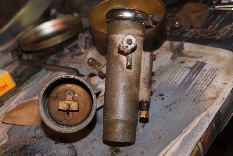
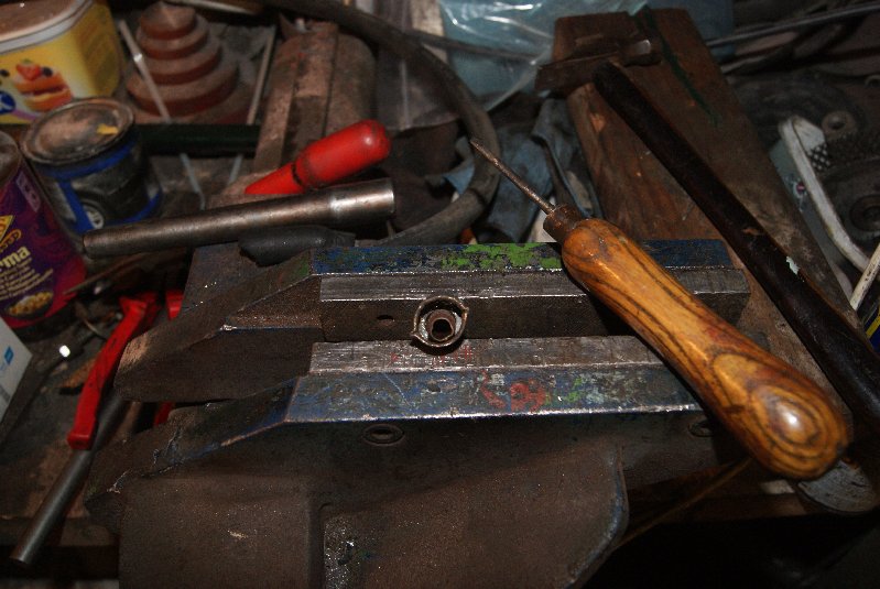
In the previous post you can see a picture of the inside of the transmission casing showing yet more of that blue paint, which looks suspiciously like RAF Blue/Grey applied over the top of the original Apple Green. I really would love to know it’s previous history, but all I can come up with was that it was sold to a machinery dealer in Northern Ireland in 1951. Did he sell it to the RAF? We may never know.June 30, 2015 at 7:56 pm #13635trusty220KeymasterRemember the picture of the carburettor with a broken off slow running jet? that’s what I’ve been up to tonight. It’s too hot to do anything outside and the workshop is the coolest place, so I took a big breath and launched into it.
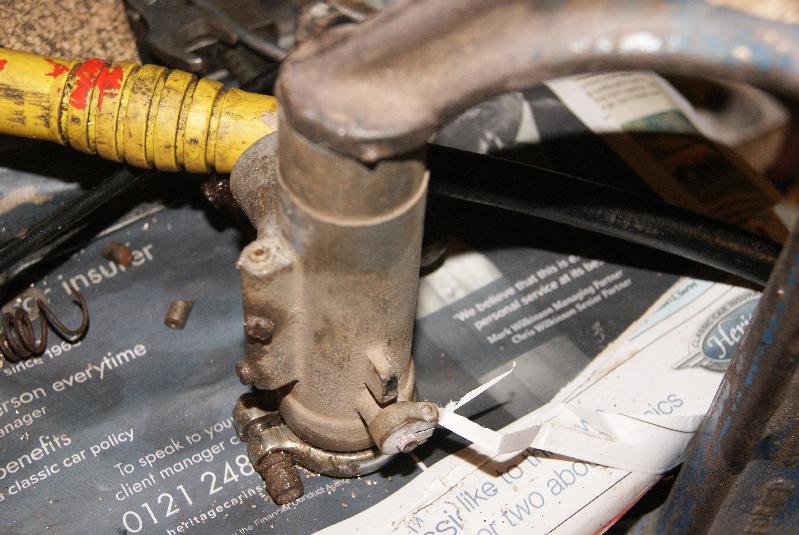
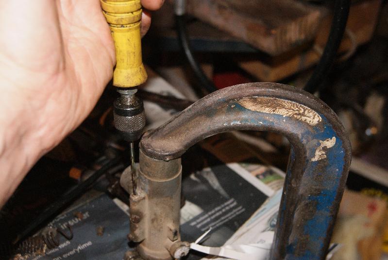
Access to it is easy enough, but it runs parallel to the main venturi pipe and so I couldn’t mount it in the pillar drill because the chuck is too bulky to get anywhere near. The solution was to use a flexible drive, very much like a scaled-down Tarpen arrangement, driven off the chuck on the pillar drill and used hand-held with some long drill bits. The much smaller chuck could just get in alongside the barrel and I took the jammed jet out in stages up to 3.5mm. You can actually see the drilled hole starting to break through to the threads in the one photo.
Next stage is to find the original size of thread and tap it out to the size, but I will have to go to my storage place to measure up my Steed to find this out.Attachments:
July 1, 2015 at 10:37 pm #13646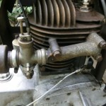 wristpinParticipant
Neat job there. I’ve got a set of anti clockwise twist drills that I keep for jobs like that and quite often they will grab the broken jet or stud and unscrew it – very satisfying!
July 2, 2015 at 6:53 am #13647trusty220KeymasterNo such luck. I’ll have to buy some!
A quick update- the thread size for this jet is 3/16″ diameter with 24 threads per inch which translates to 3/16 Whitworth. I’ve got plenty of taps for this size, so full speed ahead!July 2, 2015 at 9:46 am #13648 hillsiderParticipant
Very neat work for a hand held drill, not much help to you this time around but worth remembering for the future is that you can get long and extra long series drills. These can be very useful in situations where the chuck cannot get close to the work using a normal length drill.
July 3, 2015 at 3:23 pm #13667trusty220KeymasterThanks for the info. I was aware that you can get longer drill bits but I didn’t trust myself with such a small diameter drill being unsupported for such a length, and I took the route shown in the pictures because I was less likely to break the drill bit off in the work if it was short and supported close up to the workpiece.
As with all of these jobs, there’s always a hundred ways to do them.
I’ve just bought a 12″ length of 5/16″ hexagonal bar to make the new jet out of, so watch this space to see if I achieve it!July 3, 2015 at 8:05 pm #13669hillsiderParticipantHaving used extra long drills a few times I can understand your trepidation, the important thing is you succeeded with your chosen method.
Get the jet right first time and you can then make some spare jets for stock out of the remaining bar, someone out there could need one then maybe you can recoup your costs!July 5, 2015 at 4:57 pm #13699trusty220KeymasterA nice thought. Judge for yourself from the photo’s whether you think you could make one for yourself, it’s really not difficult.
Anyway, onwards and upwards; a good day today.
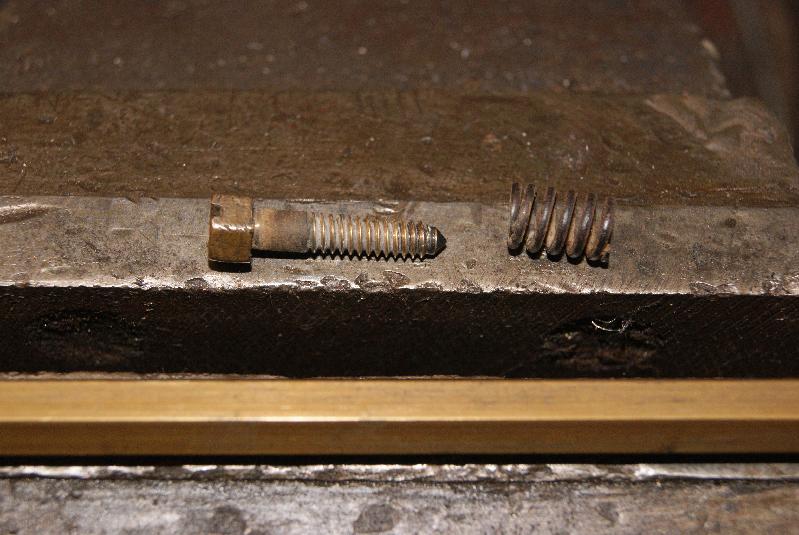
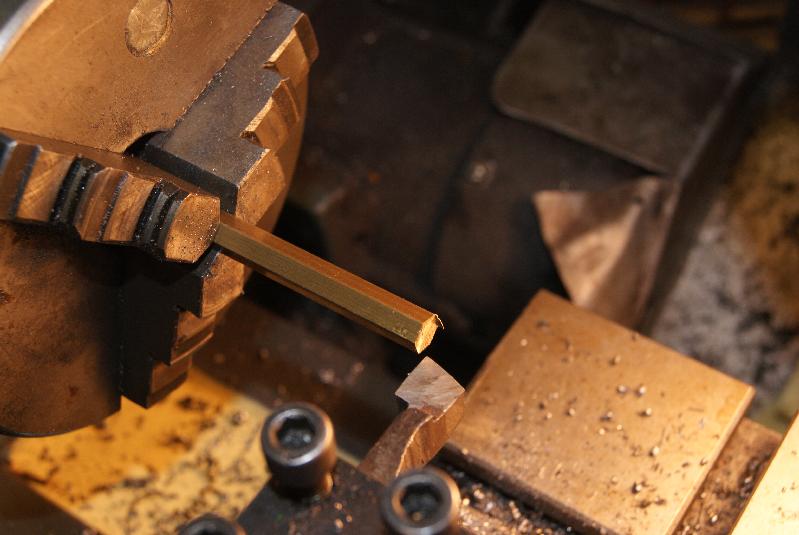
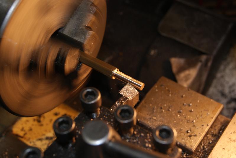
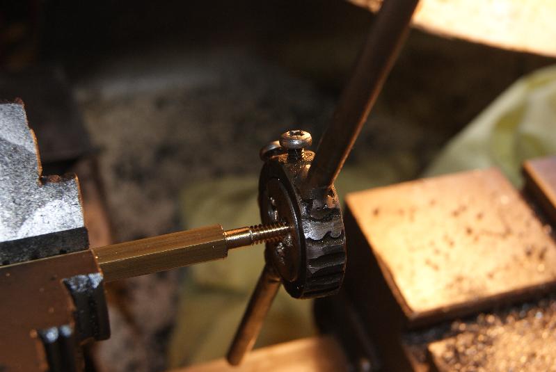
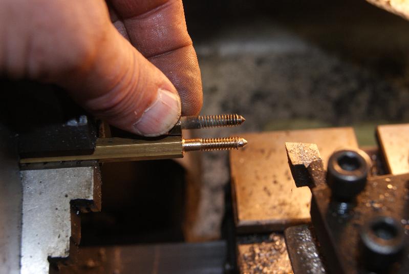
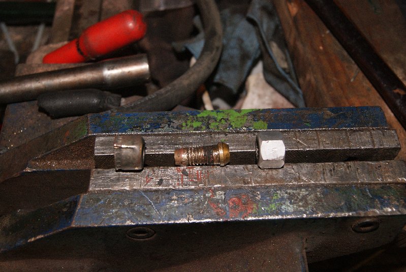
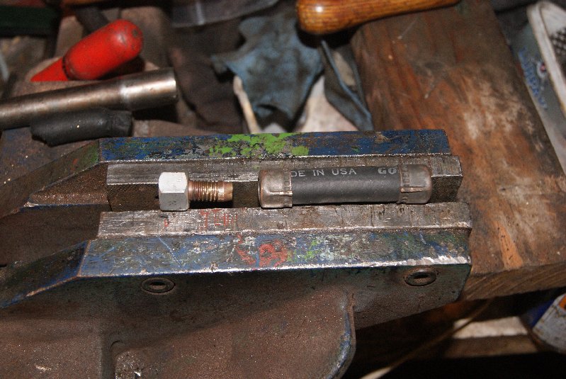
You will see the different stages of making the slow-running jet from the photo’s, but basically you start with hexagonal brass bar 5/16″ across flats. Mark off the length of thread and shank and turn it down to the external thread size- in this case the thread is 3/16″ Whitworth, so you turn it down to 3/16″ or .185″.
I chose to put the thread on by hand with a die in this case because the thread is tiny and my eyesight is non too good on the small sizes to cut it with the lathe. The result was acceptable, so to finish the end off I turned a cone onto the tip of it and relieved the thread back about 1/16″ to copy the original.
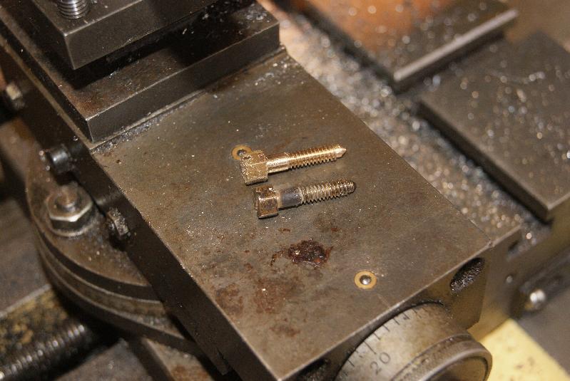
Next job was to part it off the bar, mount it in the vice and hacksaw a screwdriver slot in the head then file it up to remove the burrs. An old spring from a Zenith carb that I had on the shelf completed the job. I hope it works!
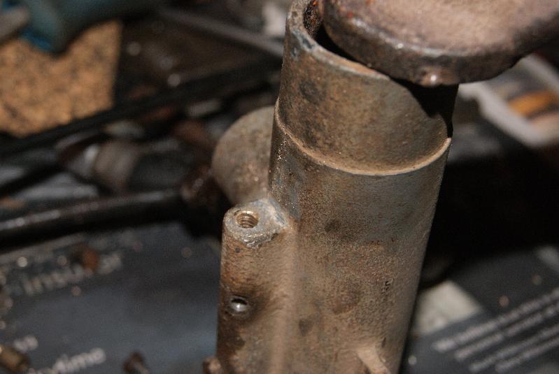
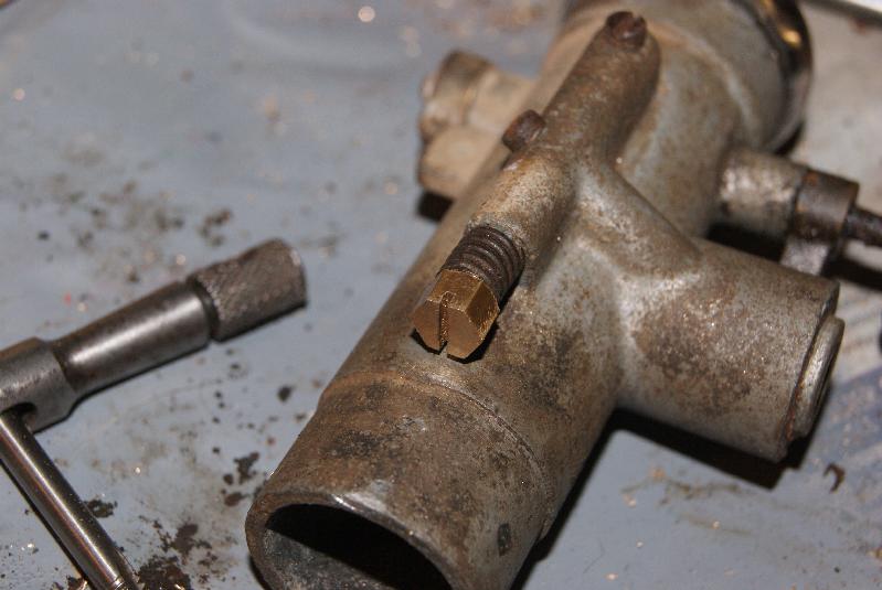
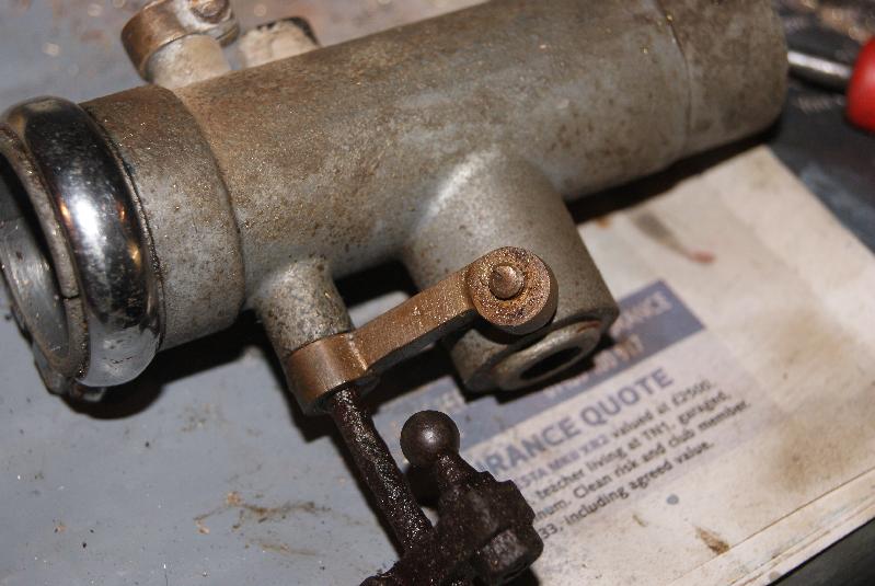
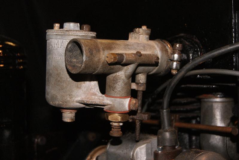
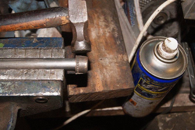
The next item on the list was the slow-running adjuster screw which somebody had twisted off some time in the dim past. It is situated on a long arm and sits against the vertical barrel that houses the main jet. When in use it is a fine adjustment to alter the angle of the butterfly in the venturi and you can’t set an even tick-over without it.
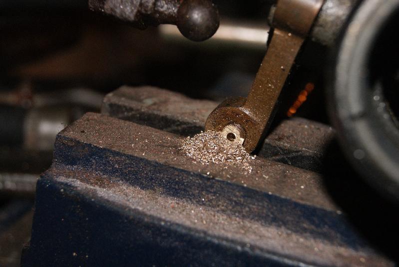
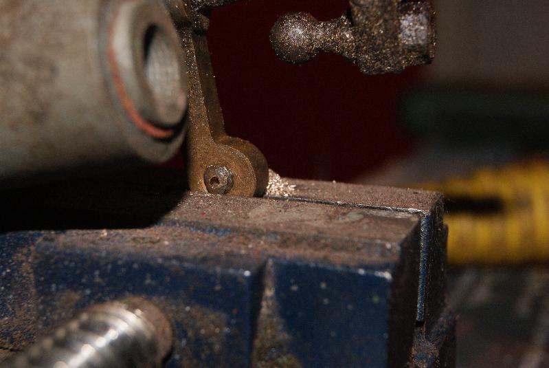
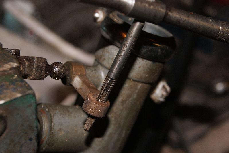
First part was to mount it securely in a drill vice, then centre-punch it and drill it using the same method as before; using progressively larger drills I was able to open it out to 1/8″, then tap it to 3/16″ Whitworth again. I found a screw in the spares box, pinched another spring off the Zenith and the job’s done!
Re-assembly of the carb was quite straightforward using new fibre washers all round, but don’t forget to take a look at the cork seal in the base of the main jet holder. It is held in place by a gland nut that compresses it when the nut is tightened; if you forget it (or lose it like I nearly did) then the carb will drip constantly from the main jet adjusting screw, so it’s quite an important little bit of wood.
Both screws were set to 1 1/2 turns out as an initial setting; these will be adjusted once the engine is running.Attachments:
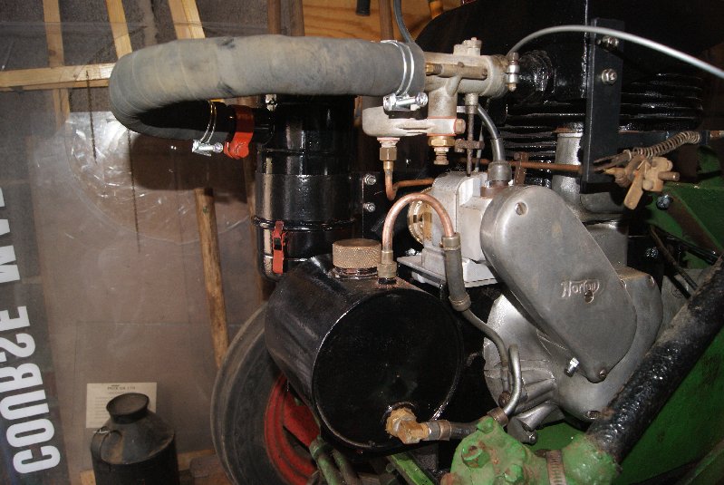
August 3, 2015 at 8:59 am #13923trusty220KeymasterI’ve got a bit of catching up to do this time, I’m afraid. Besides other things getting in the way I have made steady progress on the project, so much so that it is finished apart from mounting the exhaust.
I will go through some of the more fiddly bits that got me scratching my head in the hope that anyone doing the same work can see how I tackled the job.
Starting from the front of the engine I decided to fit a new pipe to connect the air filter to the carburettor. This sounds easy, but I couldn’t find one with a suitable sharp bend in it and so I opted for a longer pipe with a more gradual curve; it may work better in keeping the airflow smoother as well, but only time will tell. It was secured at both ends with wire clips like the original was, not with jubilee clips which are definitely a much later idea.
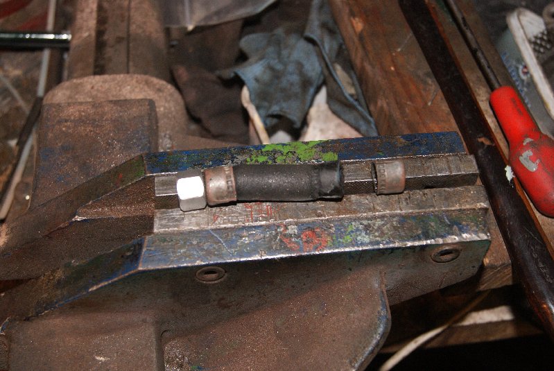
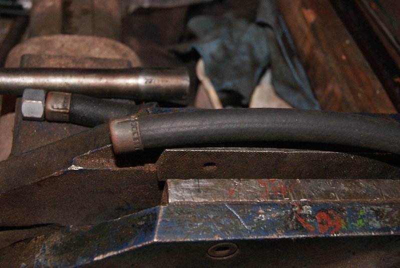
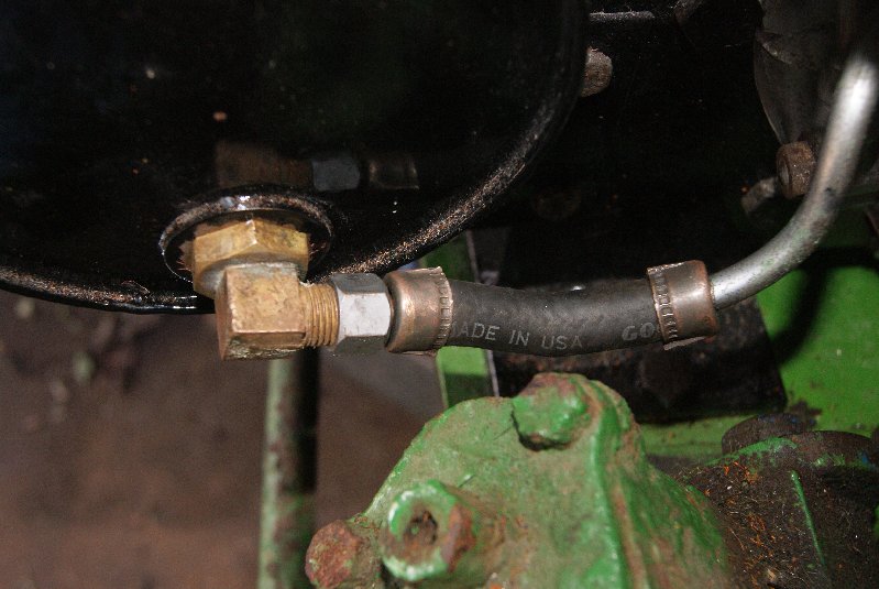
Next to follow was the oil tank and it’s plumbing; this was something that I was dreading because the pipes are designed with an anti-vibration rubber joiner in them. Needless to say, the original rubber had become porous and brittle and wouldn’t have done the job for much longer if I’d left them alone, so back to the spares box to see what I could find suitable. A length of flexible diesel tubing came to the rescue and I thought that if it was suitable for diesel then it should be fine for engine oil. Do I just put it on and find some clips to secure it? I think you know the answer to that one- NO!
These pipes are similar to hydraulic pipes in that they have swaged ends and one of them has a swivel fitting to screw onto the tank outlet. Fortunately the rubber was so brittle that it could be picked out a little at a time to leave a clean surface inside, so I then mounted the swaging onto a round bar and hammered lightly until the swaging expanded very slightly, just enough to get the new pipe in. Once the rubber pipe was in I then tried the copper oil pipe in the centre for a trial fit and couldn’t get it out again it was such a tight fit! Counting this a success I then did all the other fittings the same way, apart from the swivel which had it’s own tail which I had to use a drift to drive in once the external swaging was in place.
I only took this course of action because the pipes do not carry any pressure, they only deliver oil to the oil pump and then return used oil to the tank; if they were to carry any pressure at all then a stronger pipe and fittings would be needed, and sourced from one of the many specialists that there are dotted around the country. Don’t be tempted to use this method on hydraulic pipework, no matter how low the pressure- leave it to the experts!
Cables were the next priority. If you can solder then you can make a cable, they are that easy; the most difficult part is getting the lengths of the outer and inner cables right, and also the fact that we are not furnished with three hands to hold everything in position whilst you solder the nipple back onto the cable. Patience and care are the keys to making a good cable; you can even use old cables if they are not too worn. That’s what I tend to do- I save old cables that have perhaps got a fray on the end but are otherwise quite sound and they provide the raw materials for making up shorter cables.
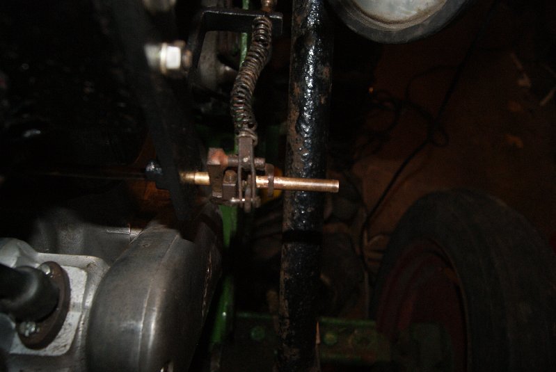
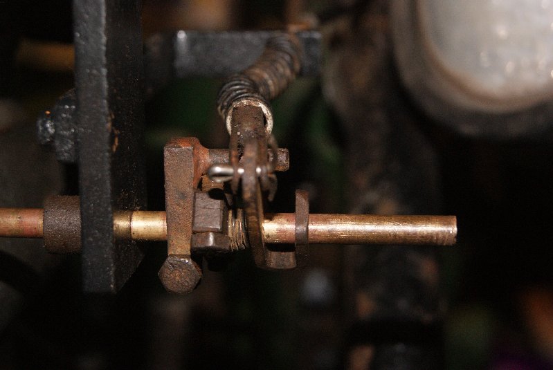
One aspect of the rebuild that really got me thinking was the arrangement of the throttle/governor linkage; how it came to me was obviously not right because somebody had added a tension spring to pull the linkage back to tick-over when the throttle was closed. How it had been assembled on the tractor looked correct but it worked the wrong way around- you could open the throttle and it would respond, but when you closed it the throttle stayed open due to a hairspring keeping the tension on the spindle the wrong way. No matter how I looked at it and turned things around I couldn’t seem to get it to work the way that I wanted until I had a Eureka moment and everything just dropped into place in a different order. I just hope it works when I fire it up!
Apart from a few more mundane run-of-the-mill bits and pieces that’s about it for the rebuild. Next time I will have re-fitted the exhaust and started it up (hopefully!).Attachments:
August 3, 2015 at 9:35 am #13936 daveParticipant
Its looking good mate. Are you bringing it to Weeley to try it out?
Dave.August 3, 2015 at 5:16 pm #13937trusty220KeymasterIt’s not mine- I’m doing it for a friend and it’s going back home to Wales this Saturday. I’ll bring a 3-speed Trusty with a plough and the 3-speed with the bogey seat and mower this time.
Update- the exhaust’s now fitted and the paintwork touched up in a few places (mainly where I’ve added pieces and the bolt heads and nuts needed some paint on). Struggling to get hold of some SAE 30 oil to put in it to start it up; if I can’t find any I’ll have to use 20W50, but I’d prefer to use non-detergent oil if possible to give the rings a chance to bed in.
Keep everything crossed!
August 3, 2015 at 8:39 pm #13942oddhatuk
ParticipantAugust 4, 2015 at 1:24 pm #13945trusty220KeymasterThanks for that but I found some at work! Because I’m on leave Monday and Tuesday I didn’t want to contact work, but when my enquiries proved fruitless I decided to call the stores manager. It turned out that he keeps some by for older pedestrian mowers (we still get a few Ransomes Auto Certes mowers in for repair) and so I went over to pick some up. It’s made by Comma and is sold in 5 litre tins with a picture of an MG TC on the outside.
Anyway, I filled the oil tank and put some petrol in the other tank, wound the strap on to the starter pulley, turned it back against compression and pulled. OWWWW B****r!!!
What I had forgotten to do was to set the magneto to fully retarded and it had stopped the engine dead, straining my wrist and making me curse.
Try again with the magneto set to retarded and after a few pulls it went. It runs rough on retard, but once it is set to advanced it settles down to a smooth tick over with a lovely crisp beat to the exhaust. I think the main reason that it didn’t fire first time is that the piston rings weren’t sealing in the barrel properly and it needs a little bedding in time. Once the petrol and oil had got up to the top end it went with no trouble at all with no adjustment necessary. Great!
Once it had started the first thing to look at is the oil return line into the tank; if it is flowing with oil then it proves that oil is getting through to the engine and the pump is working properly. If the scavenge side is working then the pressure side to lubricate the engine must be as well.
Idle curiosity led me to tinker with the idle mixture screw; it did exactly what it should do in that it caused the engine to misfire as I wound it in, and so I wound it out again until the smoothness returned. I then turned it out until the engine ran rough again, then halved the amount between the two limits and left it at that. It is an important adjustment in that it not only controls the petrol/air mixture on tick-over but it also controls how the engine picks up when the throttle is opened; there is a series of pin holes drilled next to where the butterfly closes, so that when the butterfly opens it progressively uncovers the holes so that a smooth acceleration is achieved. If you adjust the jet to give a lean mixture on tick-over you run the risk of compromising how the engine accelerates.
Anyway, it runs! Just a few small leaks on the carburretor where I replaced fibre washers and so I’m hoping that the petrol will swell them to seal the drips. Back to Wales on Saturday with it, let’s hope we get good weather on the day!
Thanks for following the rebuild, I’m sorry that it’s taken so long. In my defence I have come across most of the problems encountered on this engine before, but never all on the same engine.
A celebratory drink is called for.August 4, 2015 at 5:09 pm #13949 vhgmcbuddyMember
Glad you got the Norton running without too many problems. Three years after starting the rebuild of mine, I have still yet to get the engine to run. I am now feeling inspired to give it another go. I did get it to blow smoke rings from the exhaust on each pull, until it kicked back and snapped the starting strap (again!!)
August 4, 2015 at 6:31 pm #13950trusty220KeymasterWhere are you in the country? Do you want me to come over and run my eye over it?
-
AuthorPosts
- You must be logged in to reply to this topic.