Home › Forums › The Machinery Forums › Pedestrian operated machines › Timing a JAP series 6 Howard Gem
- This topic has 12 replies, 7 voices, and was last updated 6 years ago by
 vhgmcbuddy.
-
AuthorPosts
-
February 26, 2018 at 10:48 pm #28073
 vhgmcbuddyMember
Hello all – finally motivated to tackle my Howard Gem – i purchased it in reasonably well restored condition, but it had not been run since as the clutch needed adjusting and the engine wouldnt turn with the handle – but that has now been remedied and so on to getting the engine timed etc.
It’s a JAP series 6 I think – on the cowl it says: “Quote engine number: 81020/4” – so if anyone has any advice on the age that would be interesting.
I have had the head off and checked that all is behaving – valves are all opening/closing nicely and the bore looks good etc etc. So a test run is needed…
What is the best way of timing these? What is the point on the firing stroke where the points should open….? is there a way of measuring down the bore of the cylinder, backing it off from top dead centre, and then set the magneto onto the timing chain at that point – with the points having just opened??
And what is the gap of the points-breaker to be set to…?
Any advice very much appreciated. Ill try and get some pictures at the weekend. Tim
February 27, 2018 at 10:09 am #28077 charlieKeymaster
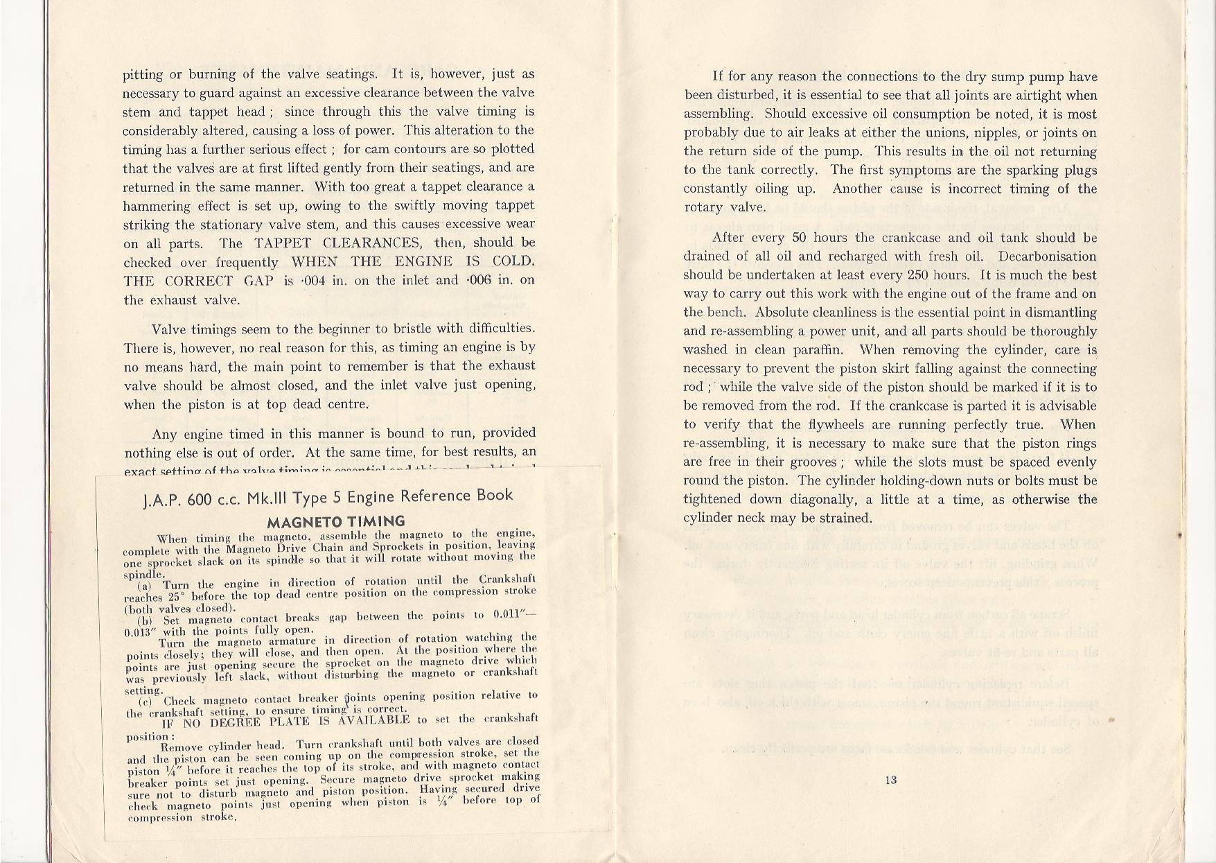
Below are extracts from manuals for the JAP600cc engine and model 6 giving details of timing.
Attachments:
February 27, 2018 at 6:51 pm #28082vhgmcbuddyMemberThat’s great thanks Charlie – i need to have a read through with these at the machine as to be honest some of it is a bit double-dutch….
February 28, 2018 at 3:14 pm #28083vhgmcbuddyMembergood move,
read as much as you can.
you are asking the right questions, it will work well when fixed.whole book, there several editions.
https://www.dropbox.com/s/8lnthdz07lflmz1/Engine%20Gem%20JAP%20600cc%20MK%20II%20Engine_Instruction%20%26%20Parts%20List.pdf?dl=0serial number as stamped into top of main frame pipe is how to date.
should be on the brass plate on rotor cover too.
then see howardgem.webs for approximate date, see where it fits in the list there.
post sn here with a pic or 2?cheers Rod.
March 5, 2018 at 7:57 am #28113vhgmcbuddyMemberMade some progress i think…
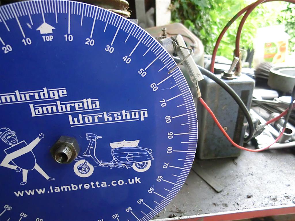
Took the cover off to the chain drive between crank / magneto and was able to take off the crank sprocket/chain. Made a little plastic indicator out of a plant label fixed to the crankshaft with the nut, and then turned the starting handle to rotate the engine through the compression stroke to TDC, and then wound it back 38degrees.
This translated as about an inch in travel down the bore – does that sound about right?
I then rotated the mag shaft until the points were just starting to open.
Put it all back together.
whizz the handle…
No spark at the mag…. the cap doesnt have a screw to hold the HT lead in place, i think it must be a push-fit, but as the HT lead itself doesnt have a brass ferrule crimped to it, it was just held in place with masking tape – so i think that needs some attention first, but with the amount of cable exposed and pushed into the mag cap it should still have been okay.
I’ll get a little wet-n-dry paper and try and clean up the points, and may as well get a new spark-plug too…
then take it from there…
March 5, 2018 at 8:21 am #28114charlieKeymasterYou may find the HT lead screws into the cap, a screw thread protrudes and screws into the wire core of lead.
March 5, 2018 at 8:29 pm #28115vhgmcbuddyMemberJust to confuse matters, the manual I have differs from what has already been provided by Charlie and Rod, stating that the points should commence to open 1/4″ before top dead centre. Don’t know how many versions of JAP engine were available for the Gem and if my manual applies to your engine.
Attachments:
March 5, 2018 at 11:09 pm #28117vhgmcbuddyMemberAh! Thanks Busman – seeing as the head comes off so easily i was thinking there has to be a simpler/more accurate way to get the points opening at the right point of compression than dicking about trying to measure degrees of rotation etc – it would be far more accurate to simply take of the head, measure down the bore that specific distance to the point of optimum compression and set the spark to come then.
As it is – having measured it by 38degrees rotation from TDC by my method described above, the cylinder is a good inch or so down the bore and this seemed too great a distance – not actually achieving a decent level of compression. Now your manual talks about 1/4″ I’m even more suspicious that what i’ve set it to can’t be right….
How can i tell what model of engine it is? The number 81020/4 is stamped on the engine cowl, but there is nothing stamped on the brass plate riveted to the “stone flap” at the back of the machine, it’s just blank…
My engine has a solid copper head gasket on which i was advised to simply heat to cherry-red with a blow torch, quench, then install -thereby “annealing” it – which I didn’t do as i didnt have a blow torch down the allotment…i just put it back together – it’s dry, no gasket sealant and didnt seem to be before either….
At the moment, there’s no spark so i’m going to try and sort that out – if i get it sparking I’ll give it a go as it is (set at 38degrees back from TDC) and if that’s really ropey then will re-do it 1/4″ down the bore….
It must just be me but i am sure the manual could have been written in a more straightforward manner.
March 6, 2018 at 4:27 pm #28118andyfrost
ParticipantDon’t try to start it how you have it at present , unless you need a broken wrist, I’m a bit miffed how you have arrived at 1″ down the bore , that is miles too far advanced , 1/4″ sounds about right , re-set it to this and give it a go , once you have got a spark.
Andy.
March 6, 2018 at 5:37 pm #28119 trusty220Keymaster
I agree- the Norton Big Four which is an equivalent to the JAP 600 uses 3/8″ Before TDC as a starting point. Don’t try it with 1″ down the bore because it will be far too advanced and will cause a kick-back.
It’s only a thought, and I haven’t timed up a JAP 600, but is there a blanking plug in the head somewhere above the piston? There is on the Norton and it’s a great help when setting it up so that you don’t have to take the head off to do the measurement.
Best of luck with it.
March 6, 2018 at 8:09 pm #28120vhgmcbuddyMemberAndy, in the manual posted by Charlie and Rod, it states rotate the engine back from TDC by 38 degrees. If the engine has a stroke of 104mm for 180 degrees of crank rotation, 38 degrees works out at 22mm down the bore, not far off an inch, which agreed sounds way too advanced. Maybe a mistake in the manual??
Sorry Tim, can’t help identifying the engine from the numbers you posted. Maybe post a photo or two so we can be sure we are all talking about the same model of engine?
Sean
March 6, 2018 at 9:23 pm #28121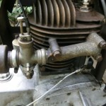 wristpinParticipant
22mm btdc is far too much. You cannot convert the linear measurement into degrees of rotation by a simple pro rata calculation. To do the maths correctly you need to know the throw of the crank and the length of the conrod.
If you are a glutton for punishment, here’s the formulaThe rod angle � is related to the crank angle � by:
R*sin(�) = C*sin(�)
R is the rod length, C is half the crank stroke.
So � = asin(C/R*sin(�))
or � = asin(R/C*sin(�))
The drop of the piston is the rod and 1/2 crank stroke minus each length times the cosine of their respective angles.
Piston drop = R + C – [R*cos(�) + C*cos(�)]
Substitute the equation for � from the above equation:
Piston drop = R + C – [R*cos(asin(C/R*sin(�))) + C*cos(�)]
Solve for � given the rod length, 1/2 crank stroke and piston drop from TDC. You can drop that equation into a spread sheet and plot piston drop versus � then put a trend line through it if you do not want to do the inversion.No, I didn’t do it from memory !!!
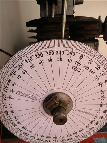
A 360 degree timing disk on the crank is the easy and safe method. You can download and print a disc from the net and glue it to a bit of card.
Sending this from the tablet but will add an image from the PC later.
Another thing to remember is that if the magneto incorporates an impulse starter the engine should be turned until the impulse trips and then turned back to set the timing.Attachments:
April 2, 2018 at 2:51 pm #28316vhgmcbuddyMemberWow, good stuff, but excuse me for not checking all the maths.
I do like these sort of technical details, you never know when it might come in handy.had a dig thru my docs, i thought i had a specs sheet for the Gem maggy somewhere,
but not to be found. maybe it is a download file, not paper.did find this, a ‘2 in 1’ JAP book,
it has same 38 degree instructions as seen, and also
with glued in insert with 1 / 4 inch instructions.it seems to me a critical instruction has been missed when reading the 38 degrees setup,
being the details which relate to “the fully advanced position”.I take this to mean that this is how the maggy is installed for proper setup of the fully advanced position for when it is running at full governed speed rpm.
it would help if the book actually stated that…the impulse mechanism then retards the maggy for starting.
again the book does not explain that, at least not on that page.the quarter inch BTDC method is the opposite method,
how to install maggy from the startup spark position,
which is the usual method for installing ignition systems by
startup timing a motor which has an automatic advance system.the specific instructions for each method are quite different,
and must not be mixed up.attached is picture of insert instructions,
and link to book cover with page 12 and page 12 insert,
also link to Wico specs sheet for maggy for the Howard Terrier engine,
the Howard Model L.
a similar type of maggy, but with different operating specs,
so only use to help understand how it works,
do not assume those specs work for the Gem maggy.notice to anybody who finds this post looking for Howard L info,
the 30 degrees BTDC is for early models with angled spark plug head,
later models with vertical centered spark plug need less advance,
make sure you have the right specs for your motor.
if rebuilding from boxes of parts, make sure you have
the correct maggy for you motor,
many look the same but have different specs.keep at it, eventually it will get sorted correctly,
and the motor will sound that much sweeter from all
the effort it took to get it right. Rod.https://www.dropbox.com/s/eczuzqk8ohata9r/JAP600mk3type5rotaryhoe-MB-H-01-maggytiminginsert.pdf?dl=0
https://www.dropbox.com/s/0nyb1k7hj1t8q4i/wipac-series81-cj1214-Howard-L-ref-B137.pdf?dl=0
Attachments:
-
AuthorPosts
- You must be logged in to reply to this topic.