Home › Forums › The Main Forum Area › Projects › Simar 56A Rototiller – Serial No. 561621
Tagged: restoration, simar, simar 56A
- This topic has 38 replies, 5 voices, and was last updated 6 years, 3 months ago by
 vhgmcbuddy.
-
AuthorPosts
-
October 24, 2015 at 11:26 am #14937
 vhgmcbuddyMember
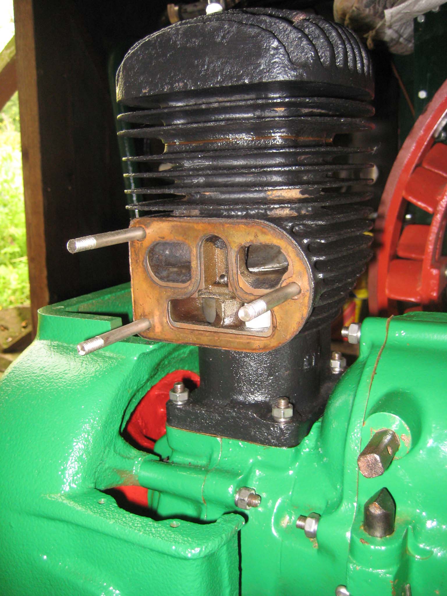
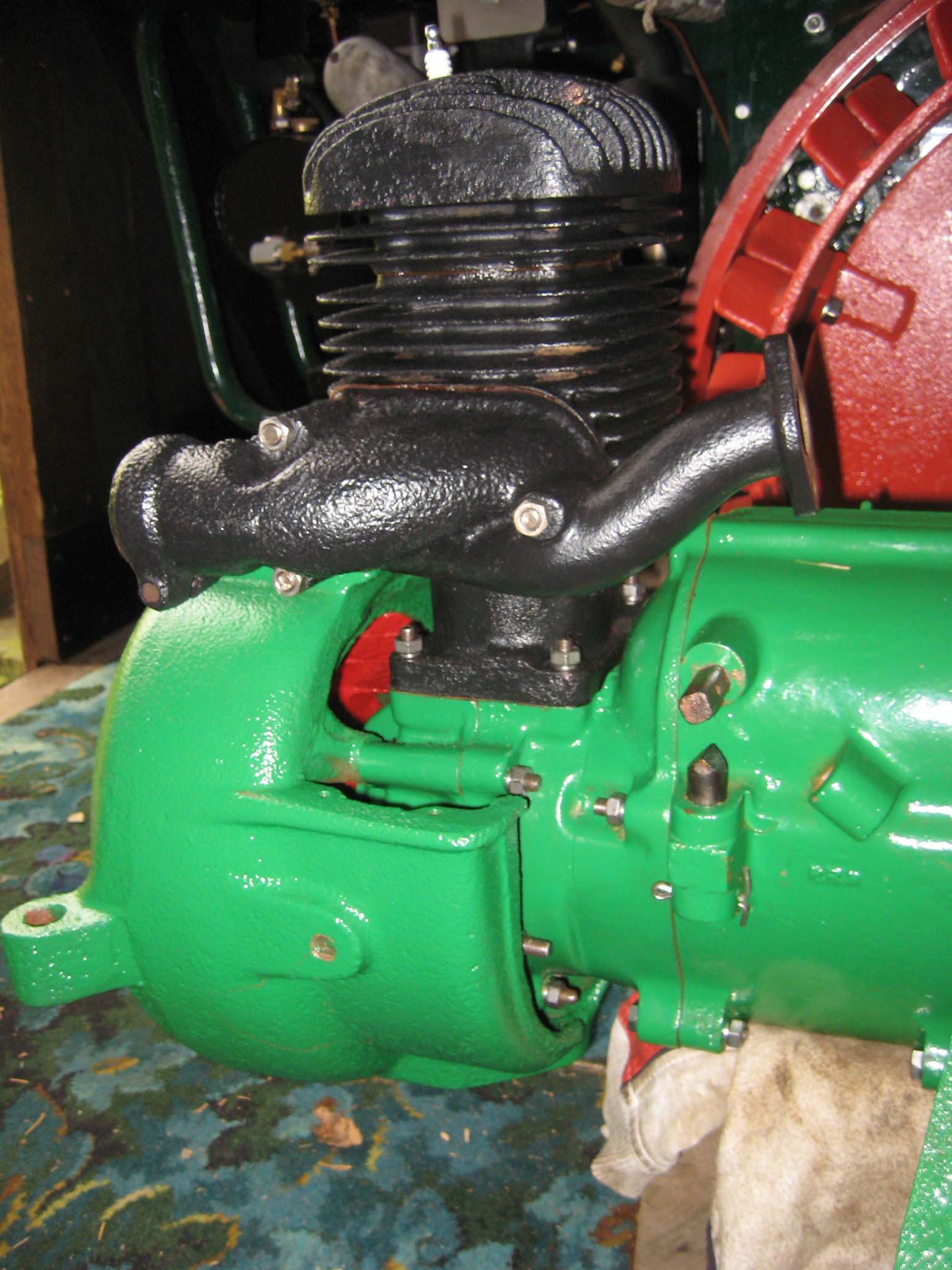
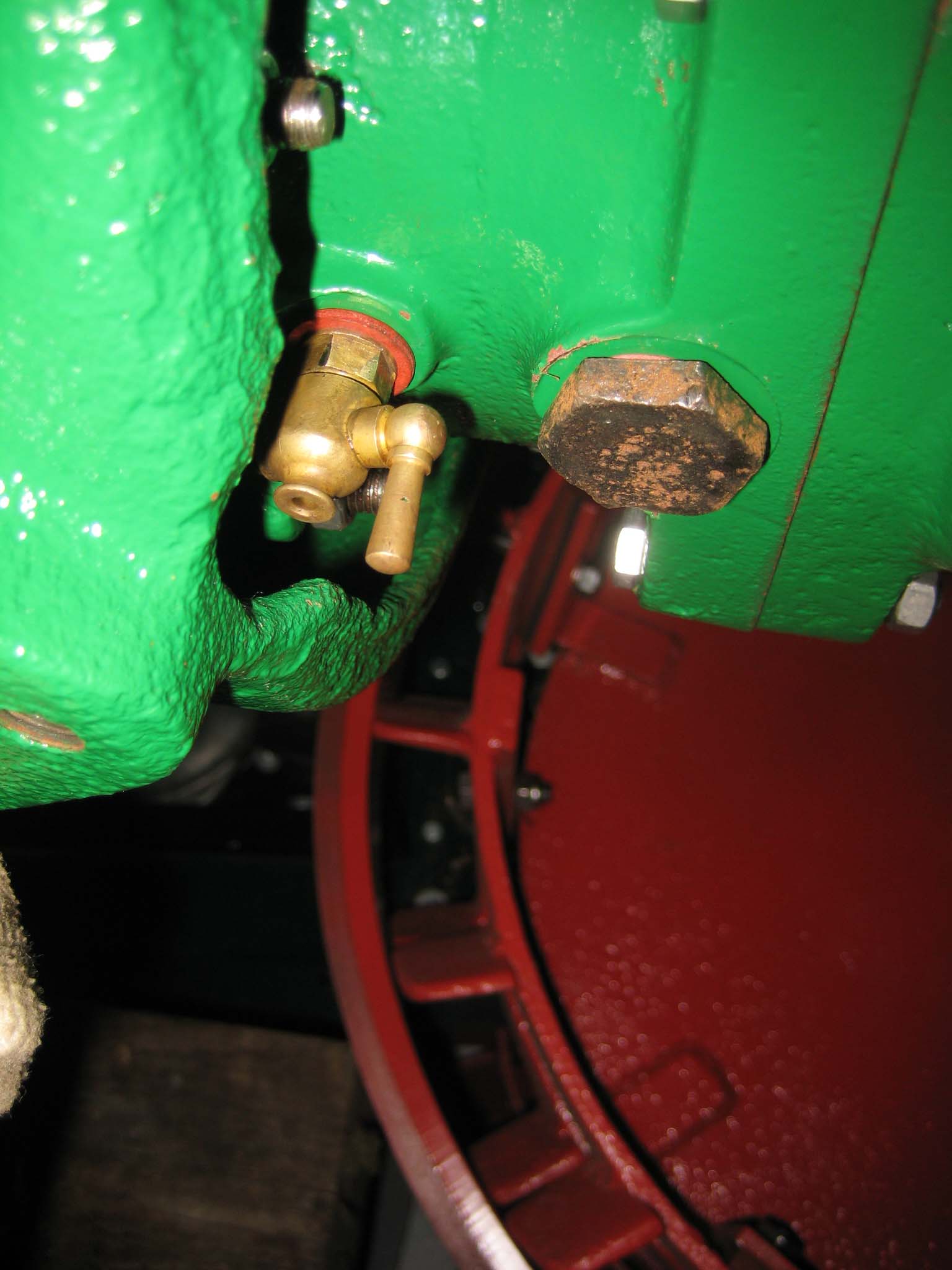
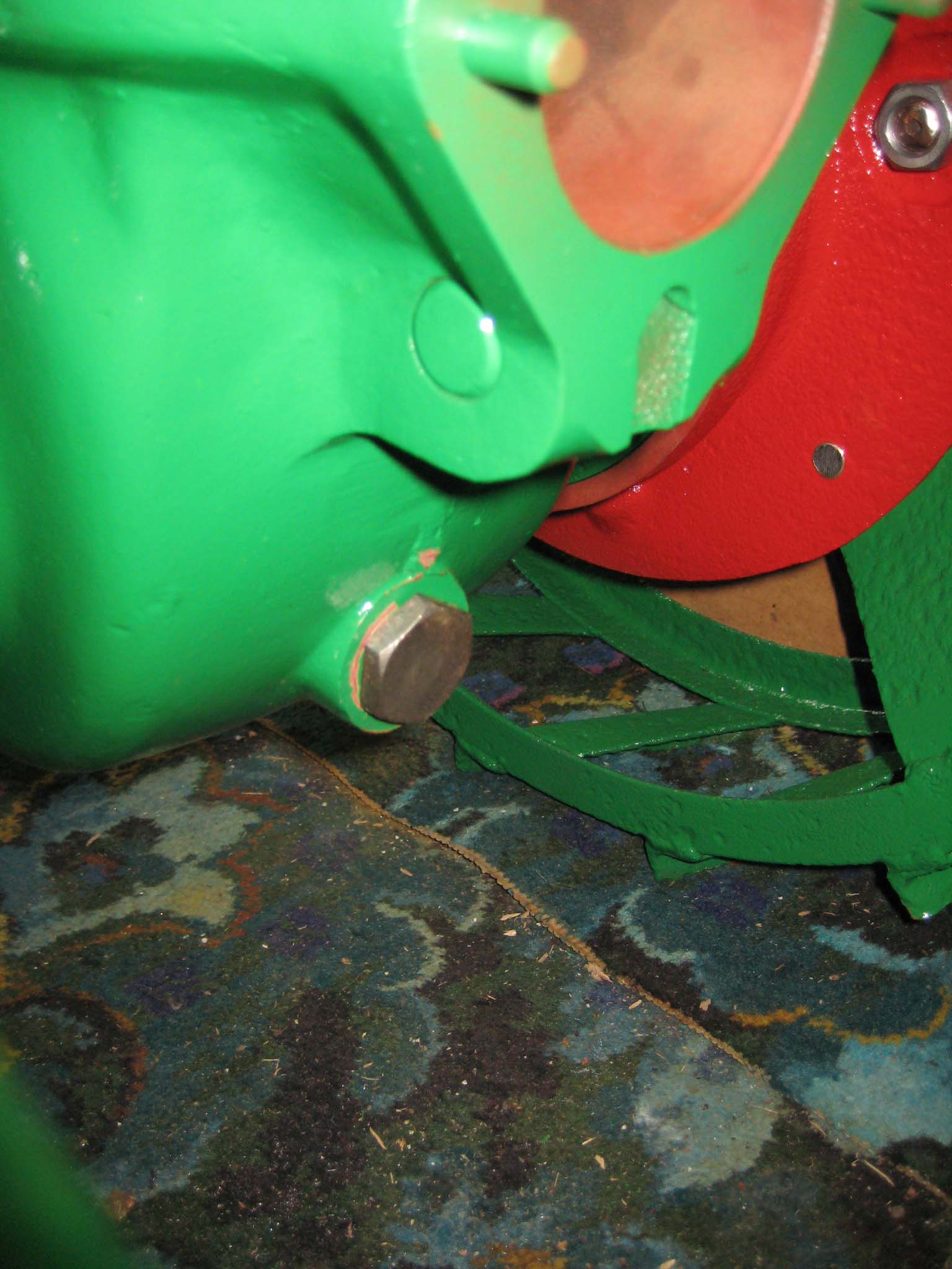
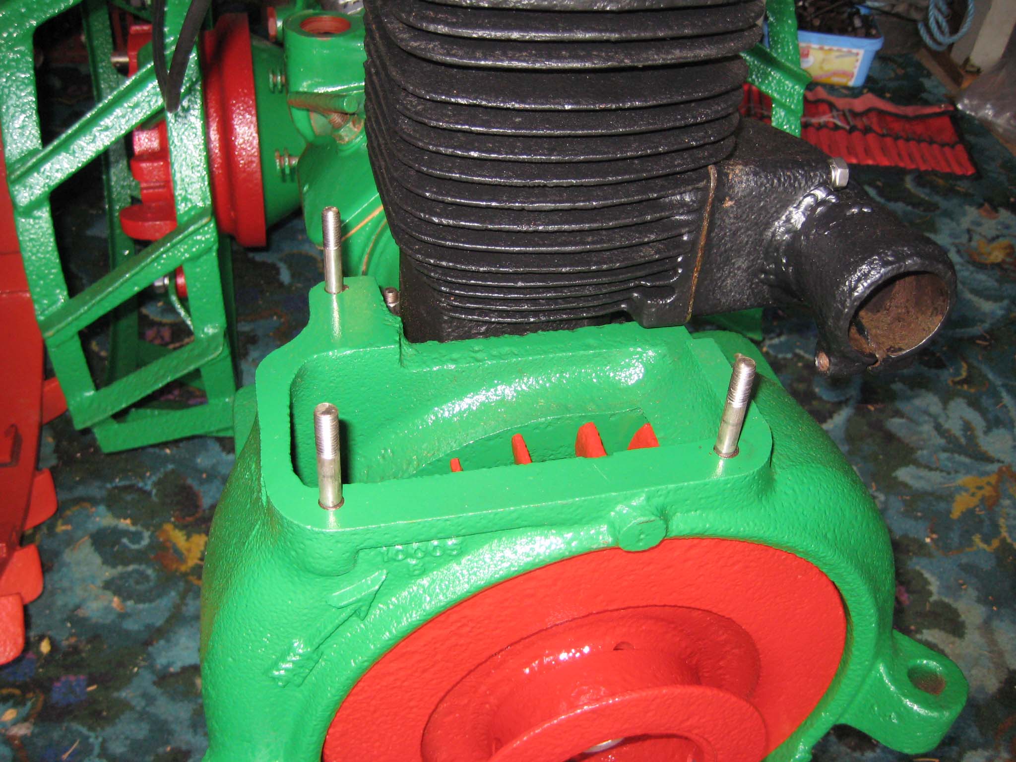
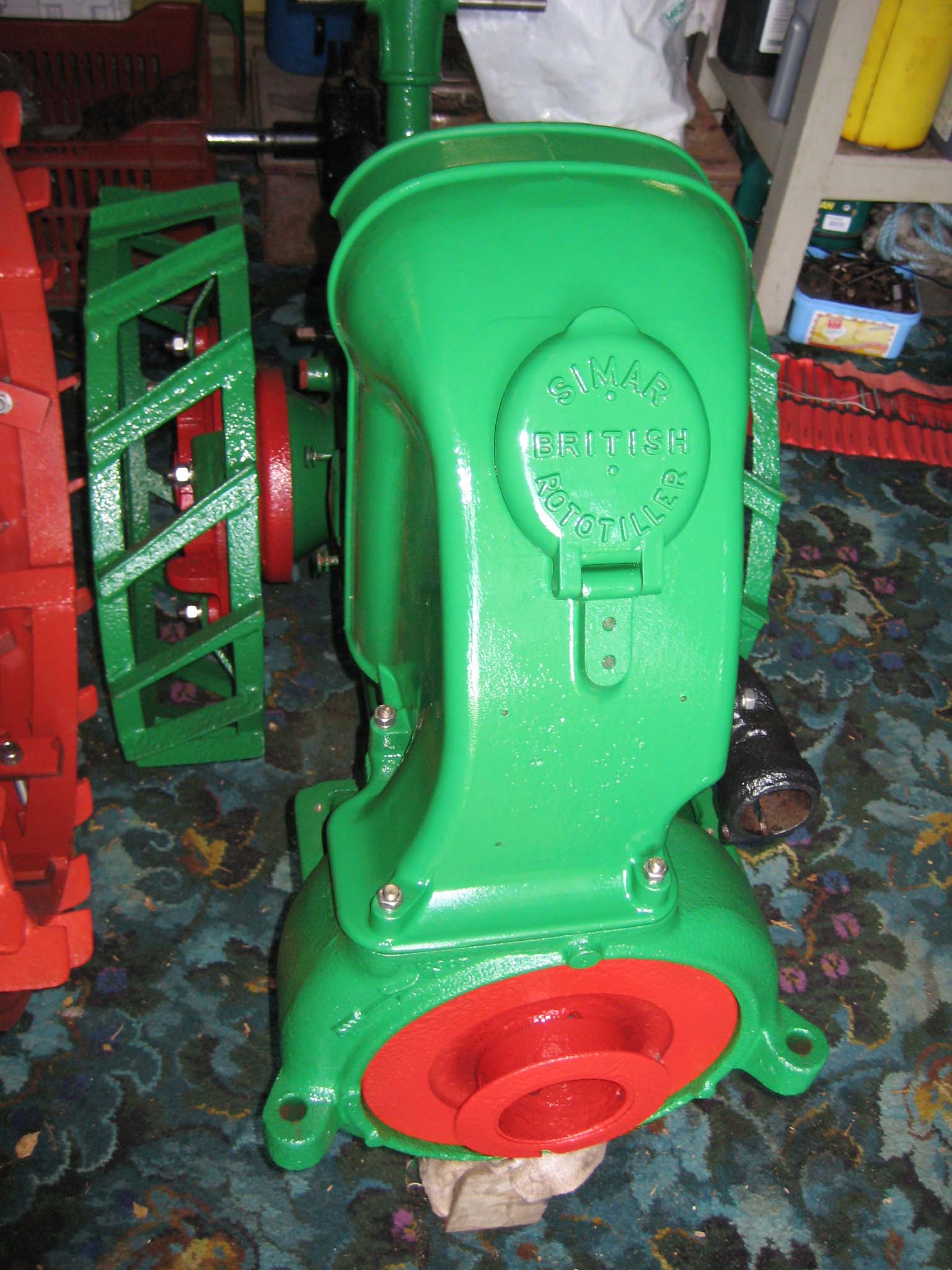
Three M8 studs were fitted into the cylinder barrel, along with the copper exhaust/air intake manifold gasket (Simar 0076), followed by the manifold (Simar 0077). The crankcase drain tap was re-fitted, along with the gearbox oil drain plug (Simar 0078). The tap would have been much easier to fit before the fan casing had been installed. There is another drain plug at the rear of the main gearbox (Simar 0079).
Attachments:
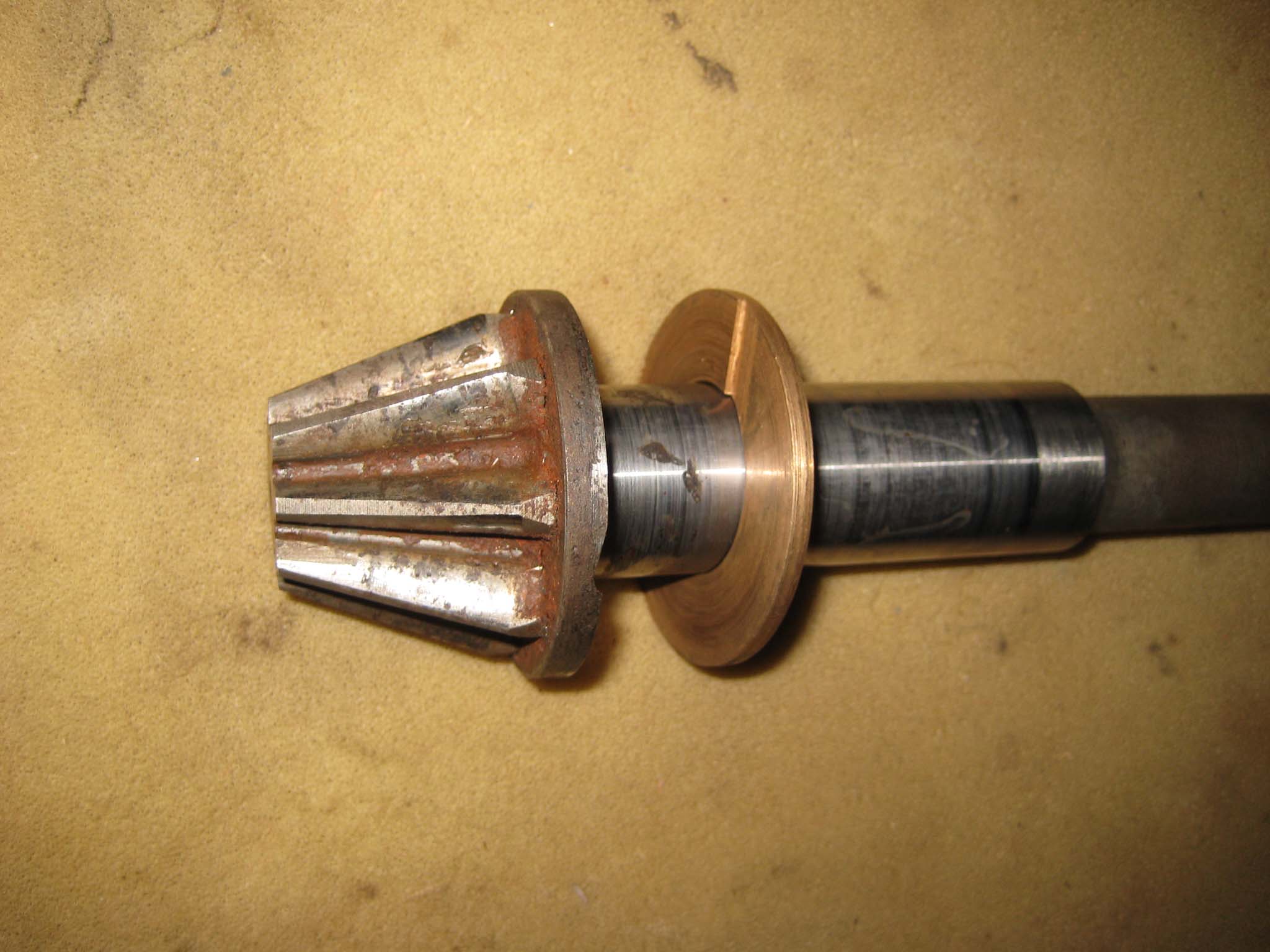
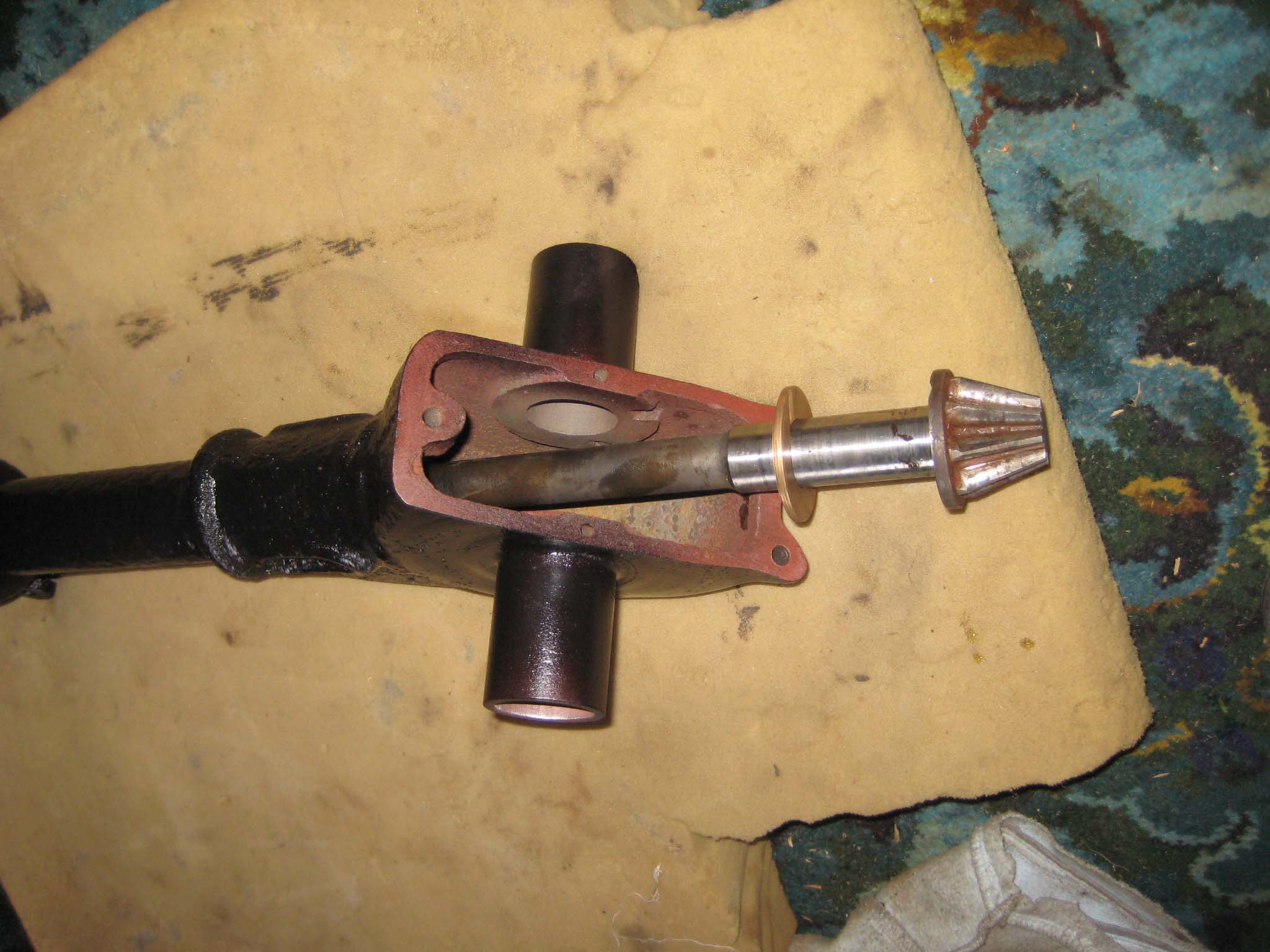
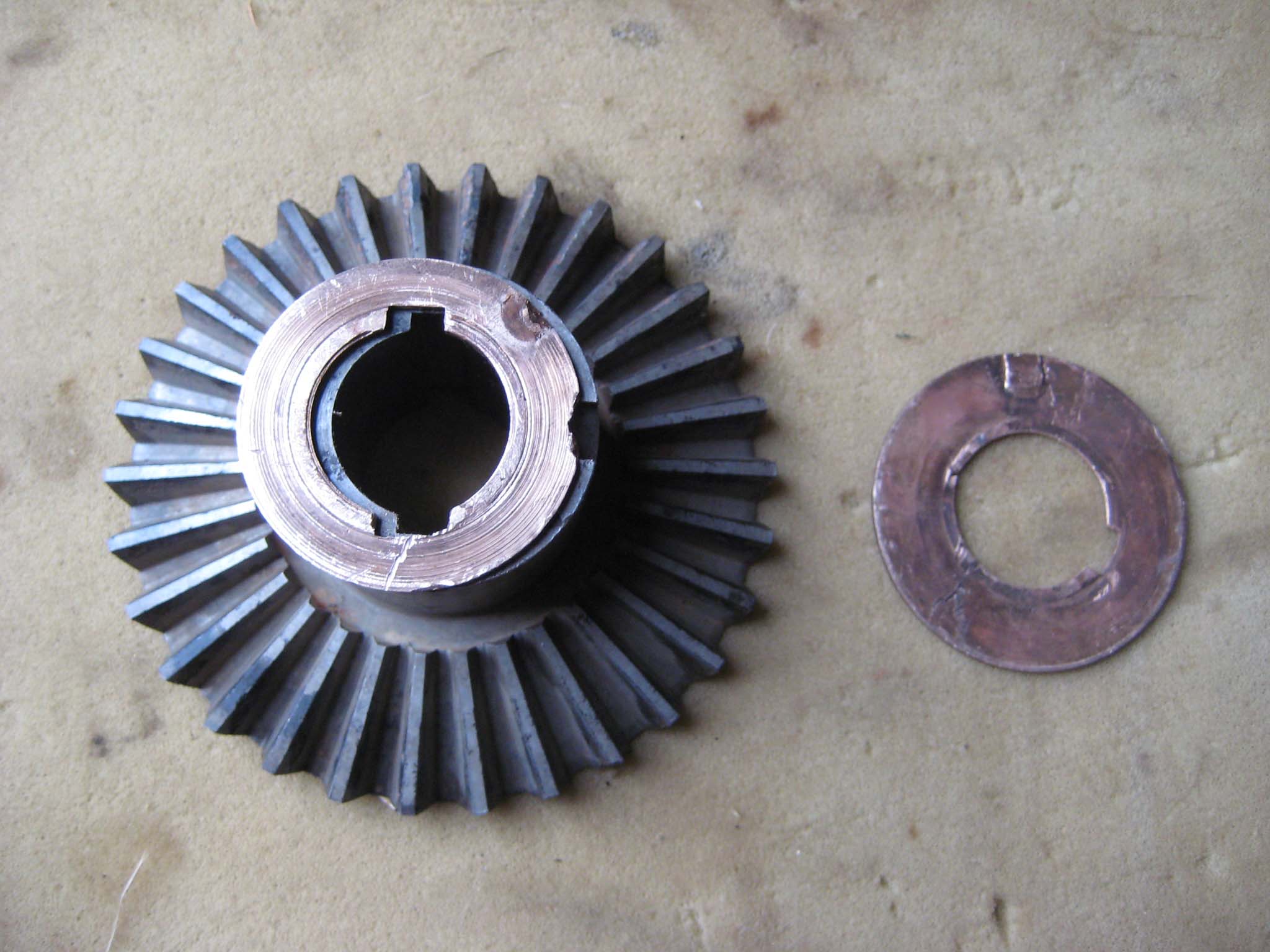
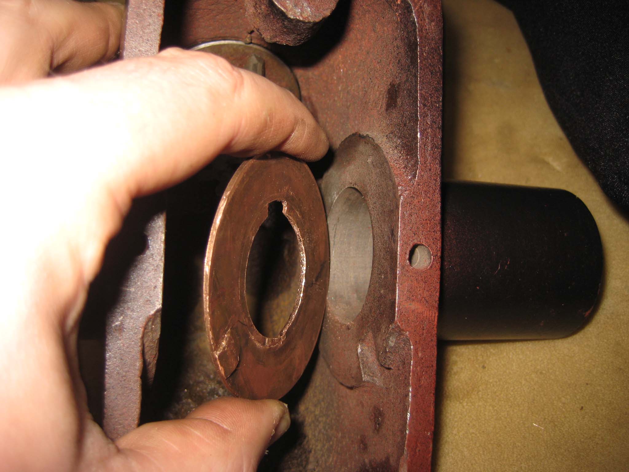
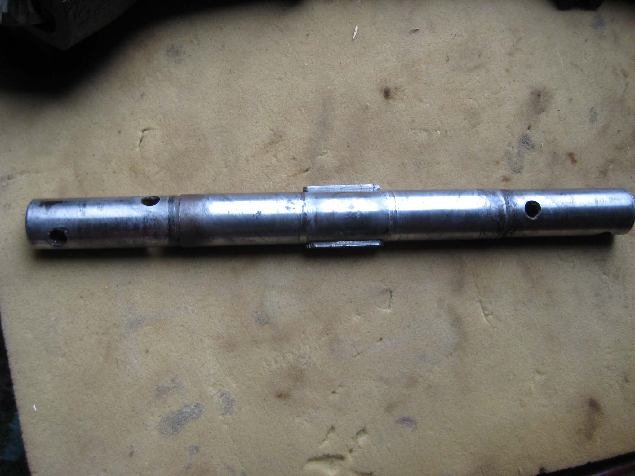
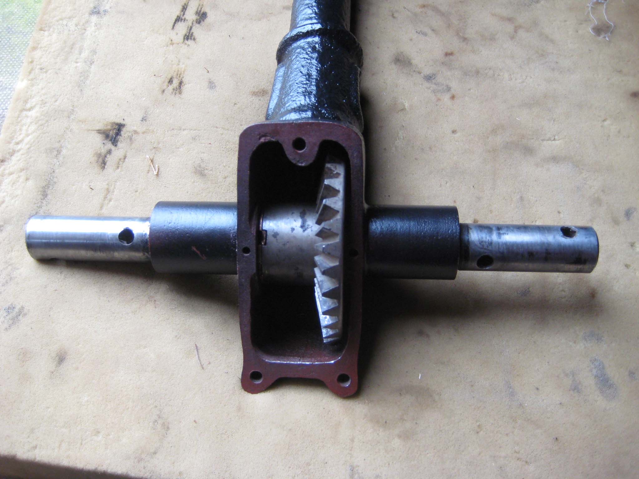
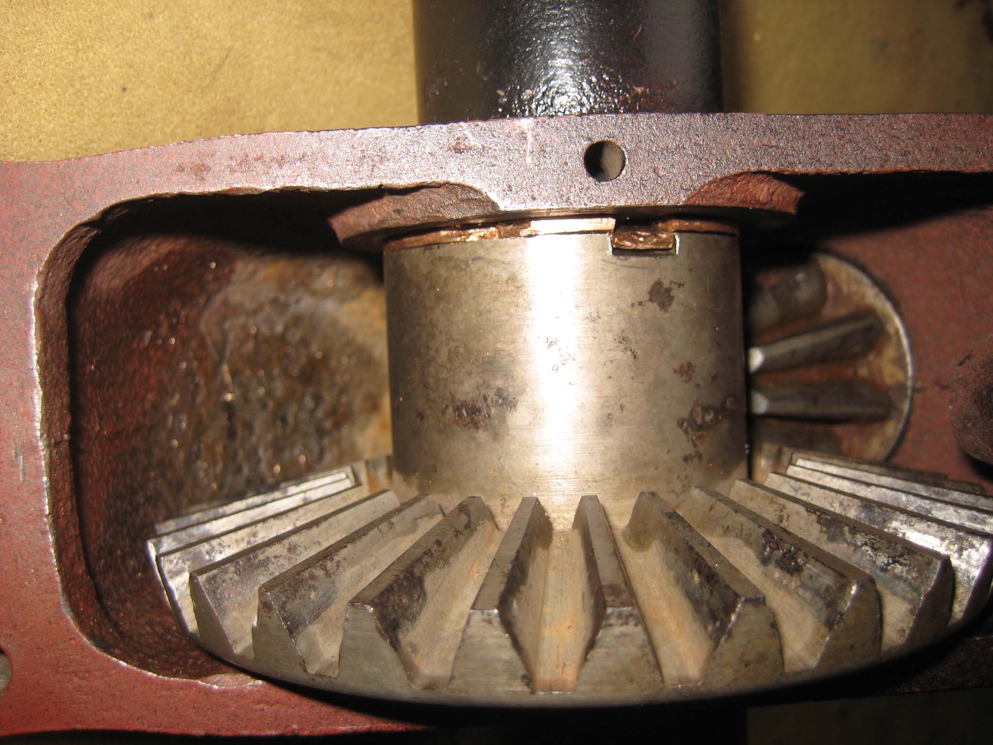
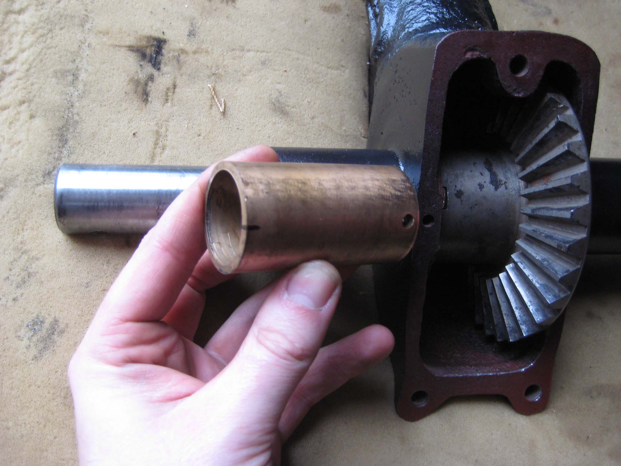
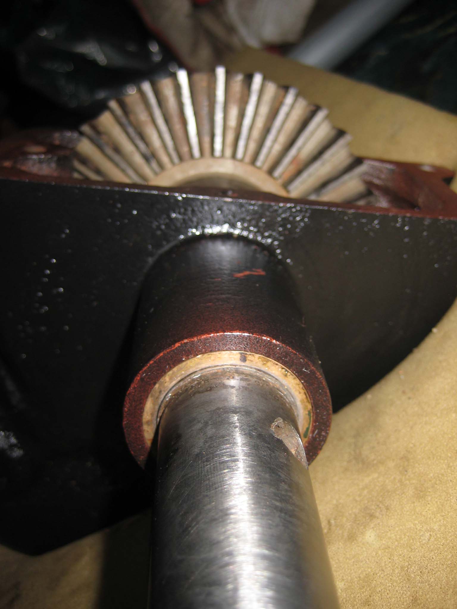
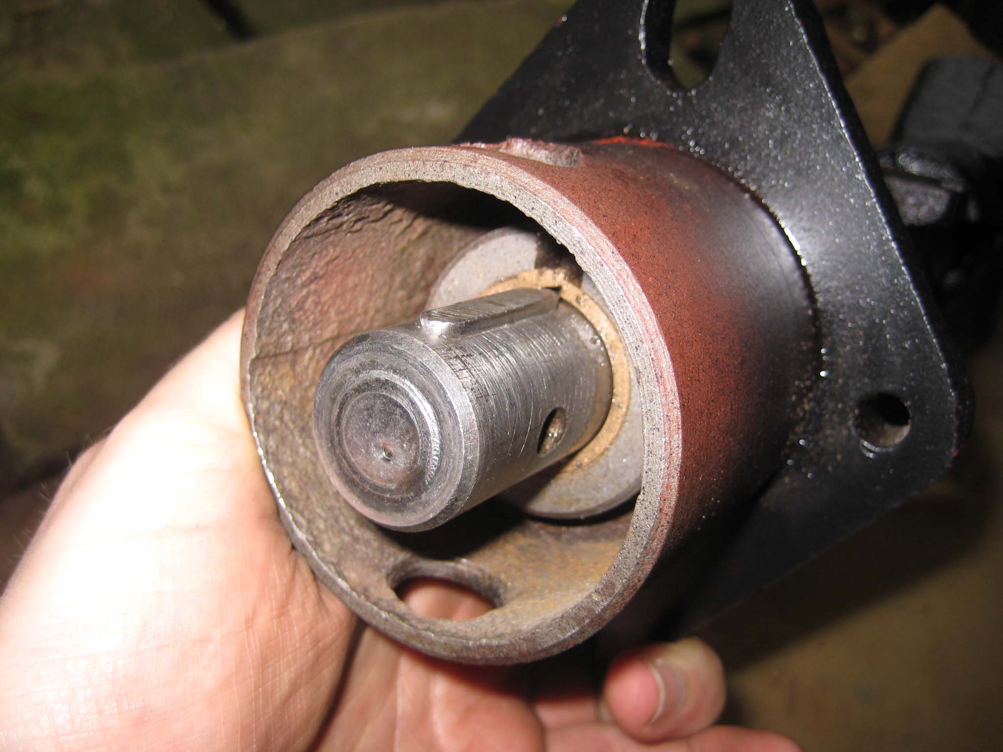
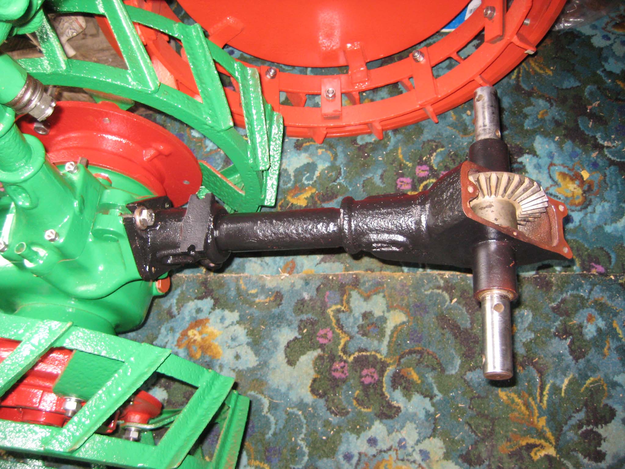
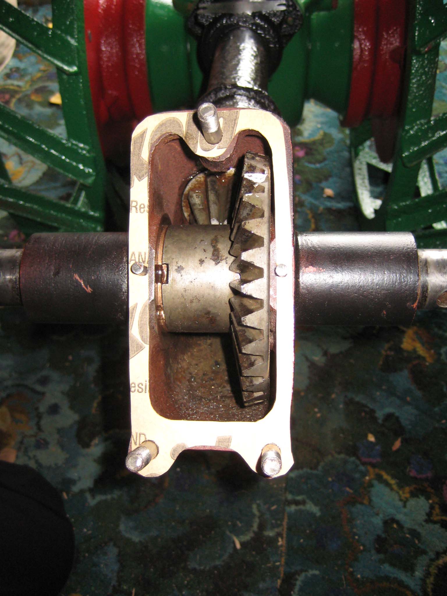
October 24, 2015 at 11:32 am #14942vhgmcbuddyMemberI next moved on to preparing the miller PTO assembly. The main drive shaft was fitted with a Steel thrust washer immediately behind the bevel pinion, followed by a Bronze thrust washer (Simar 0080). This was then fed through the Bronze bushes in the miller casing (Simar 0081). The crown wheel has thrust washers on either side. The left hand washer has cut outs in it to allow the keys on the miller cross shaft to pass through when the shaft is removed/installed. These are not visible when the unit is assembled, but there is a ‘V’ notch cut in the circumference of the washer which once lined up with a notch on the crown wheel indicates that the washer is correctly aligned for removal/installation of the cross shaft (Simar 0082). The right hand thrust washer includes a tab which sits in a notch on the inside of the miller casing, to ensure the washer does not spin against the casing wall (Simar 0083). Keys were fitted to the cross shaft (Simar 0084) and the shaft driven through the crown wheel from the left (Simar 0085). With the cross shaft in place, the left hand crown wheel thrust washer needs to be rotated by inserting a flat bladed screwdriver into the ‘V’ notch and gently tapping it around until the locking tab on the washer lines up with the notch in the crown wheel. Bend the tab over into the notch, so the washer will spin with the crown wheel (Simar 0086). The miller cross shaft bushes where then pressed into the casing. The bushes have a hole at one end which needs to align with a corresponding hole in the casing (Simar 0087 & 88). A pin will be installed later. The key was fitted to the driven end of the PTO shaft (Simar 0089) followed by the miller dog. The dog is held in place by a 6 x 50mm roll pin (Simar 0090). The miller PTO assembly was then bolted to the rear of the machine (Simar 0091).
Attachments:
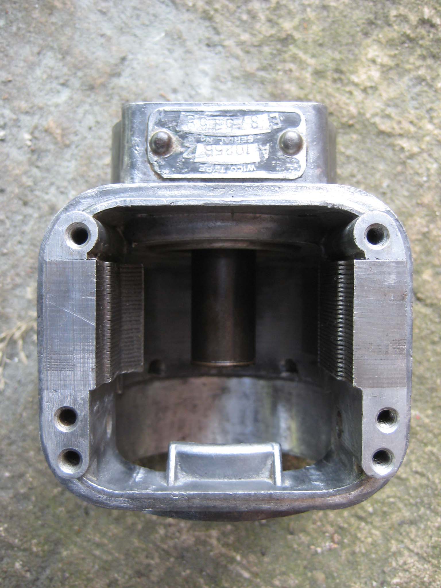
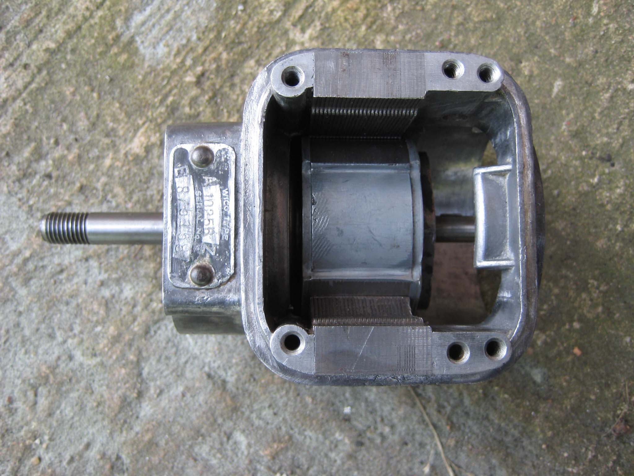
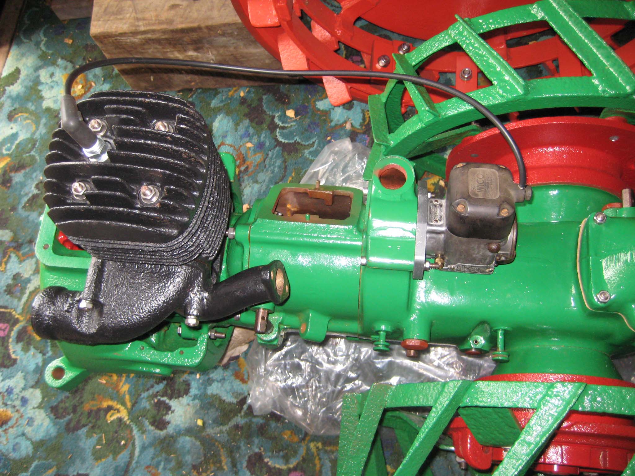
October 24, 2015 at 11:39 am #14955vhgmcbuddyMemberI now focused my attention on the magneto. My Simar 56a is fitted with a Wico Series A magneto, type A10258Z. I took the plunge and decided to treat it to a full strip down and refurbishment. The following details the rebuild.
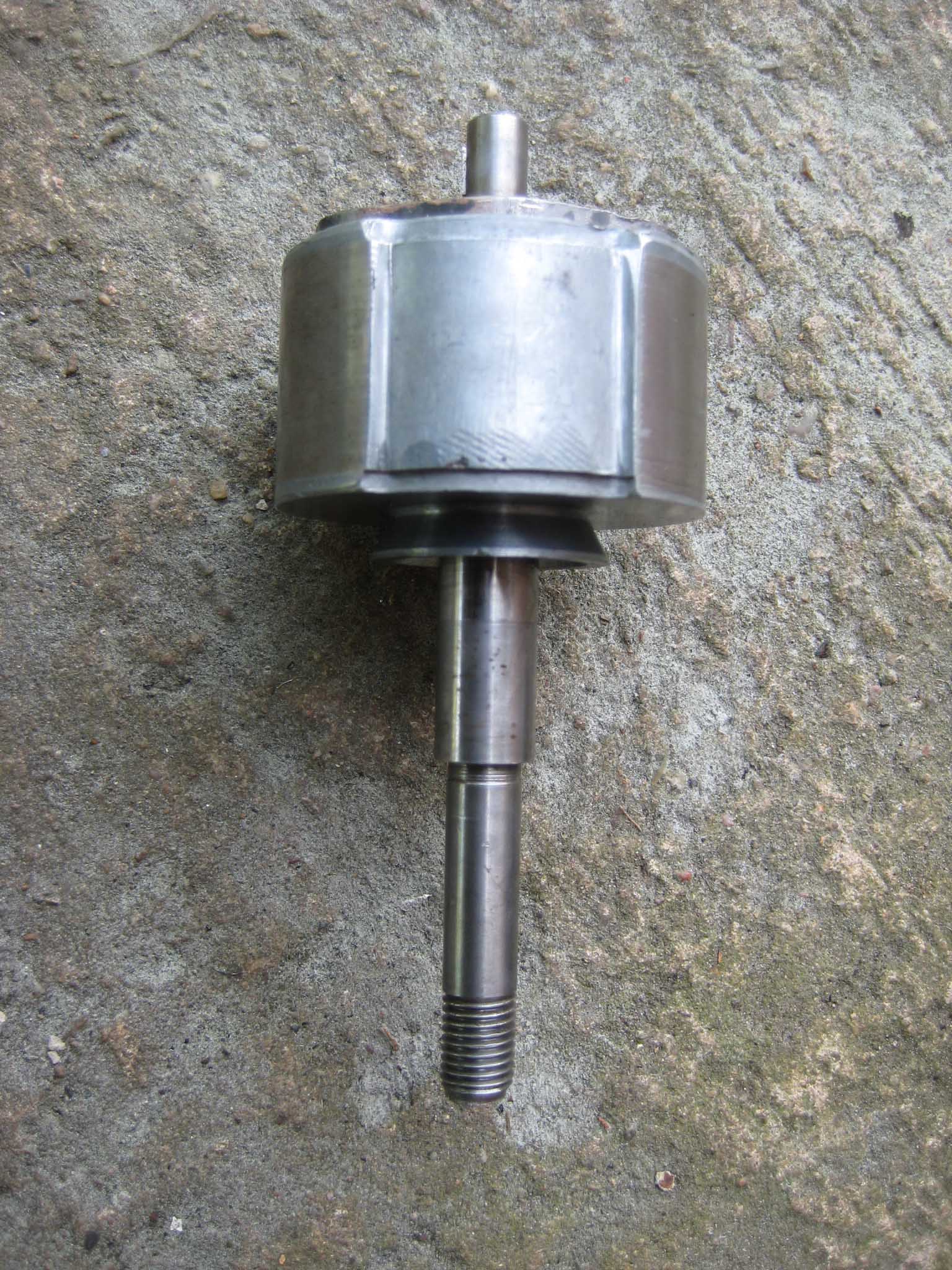
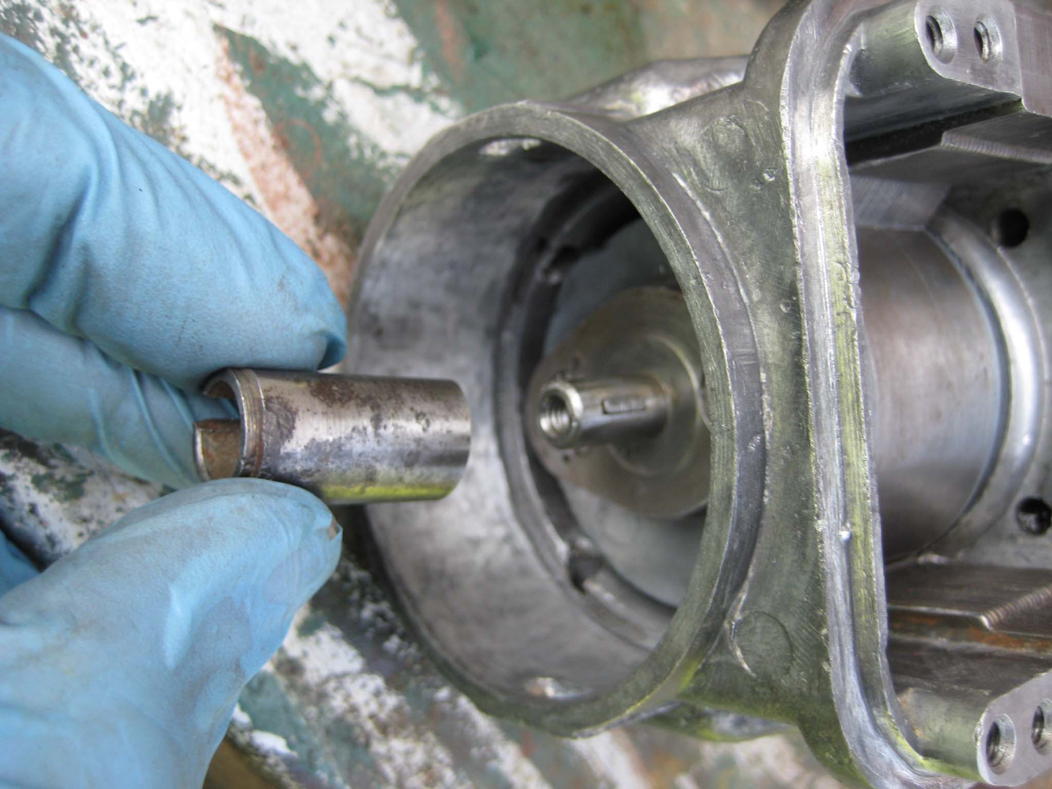
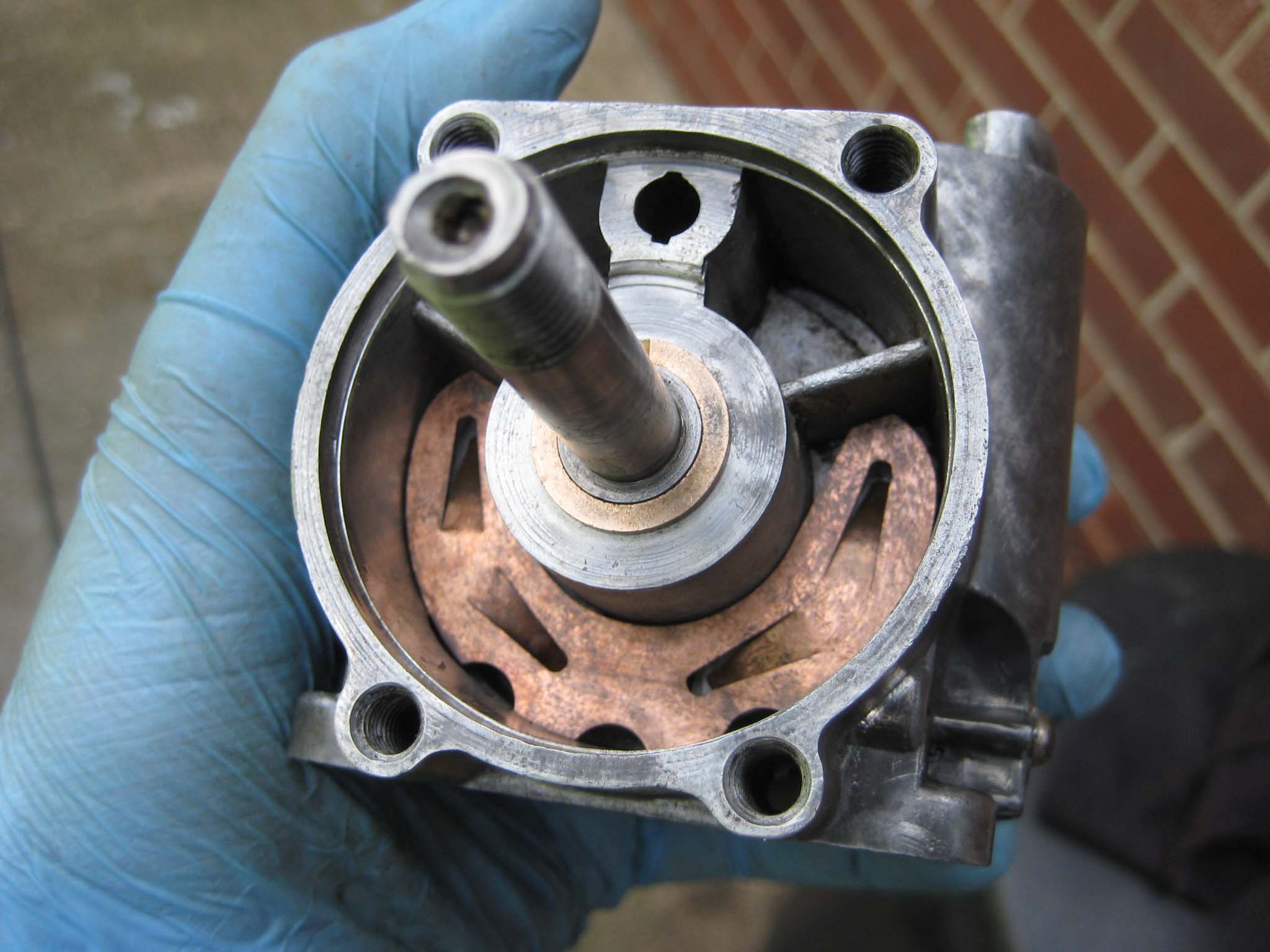
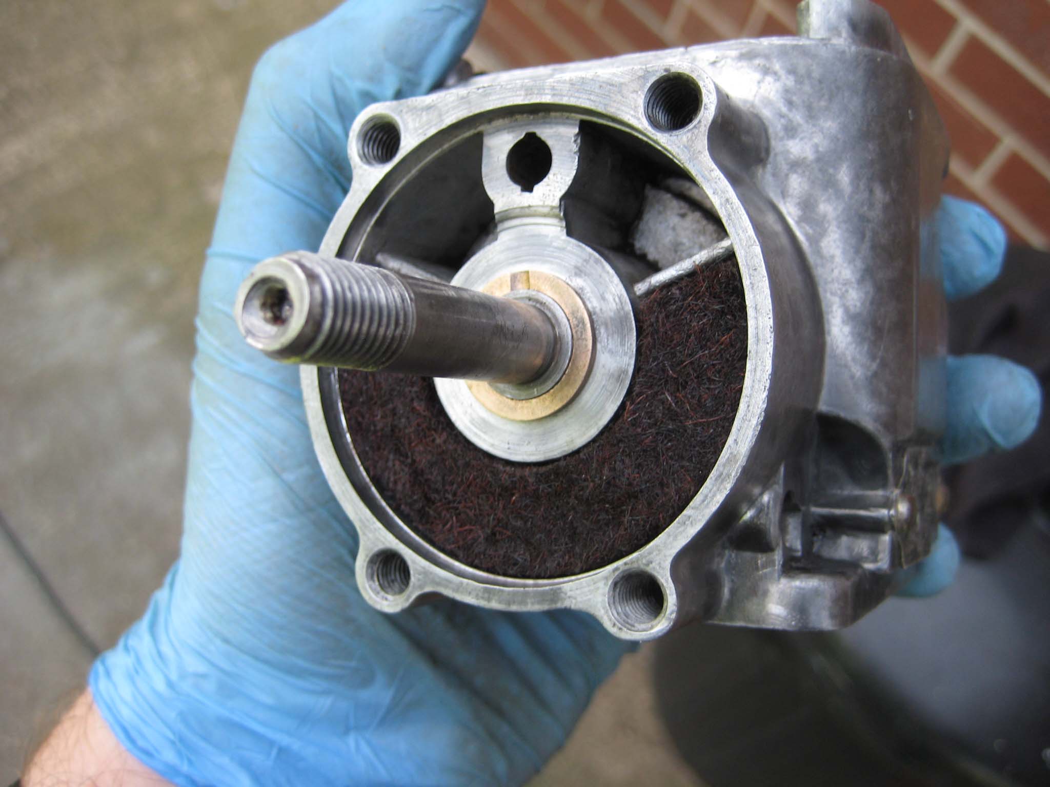
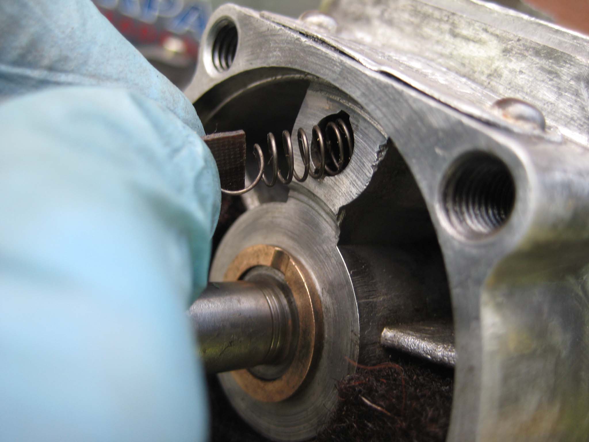
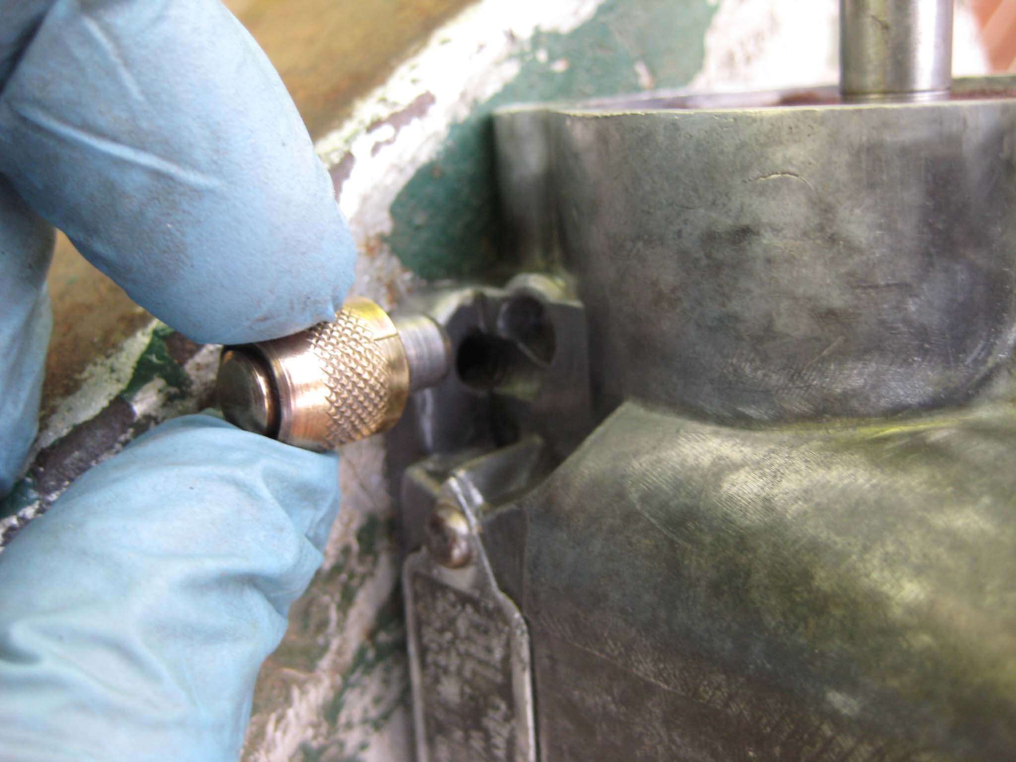
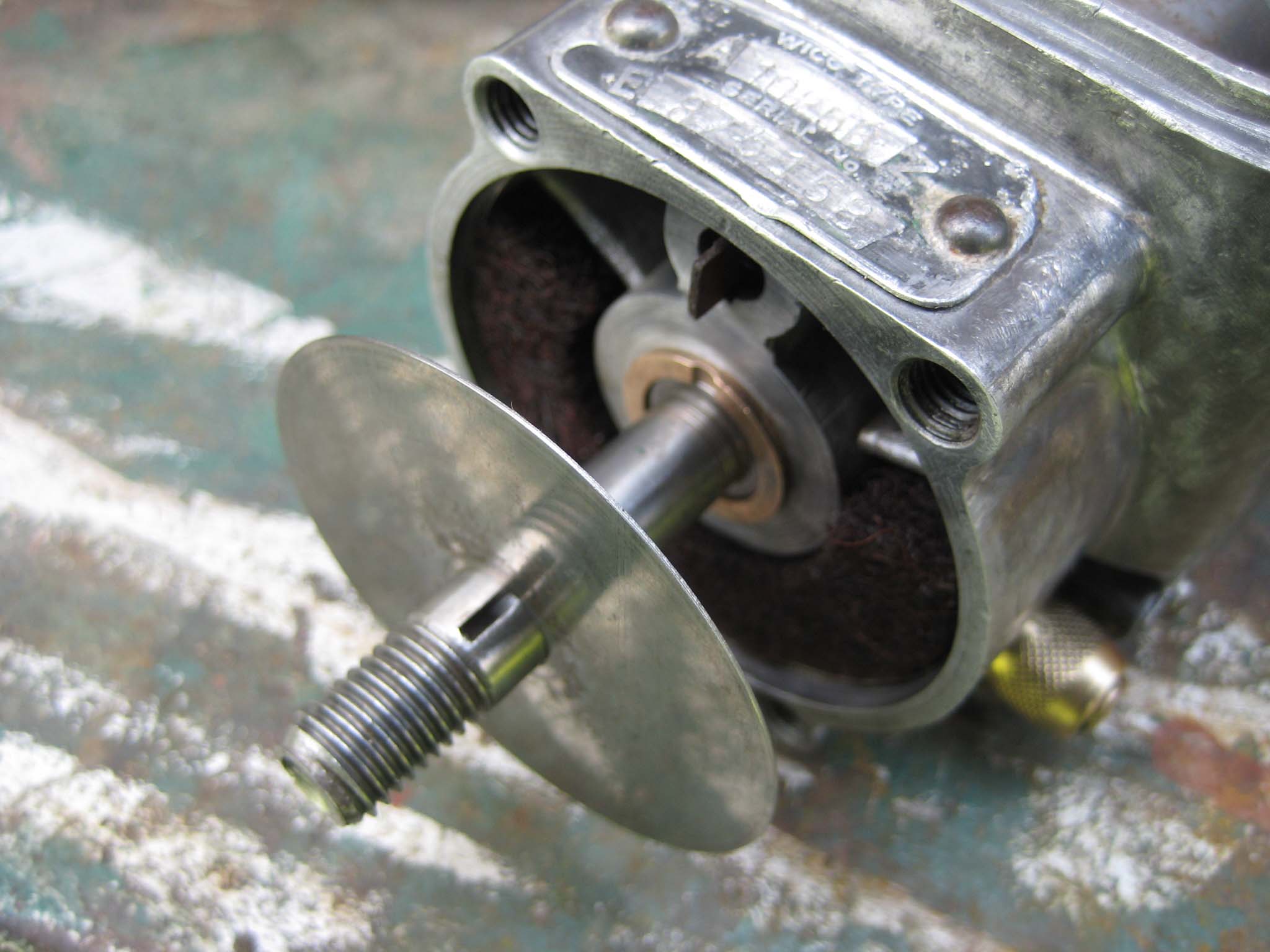
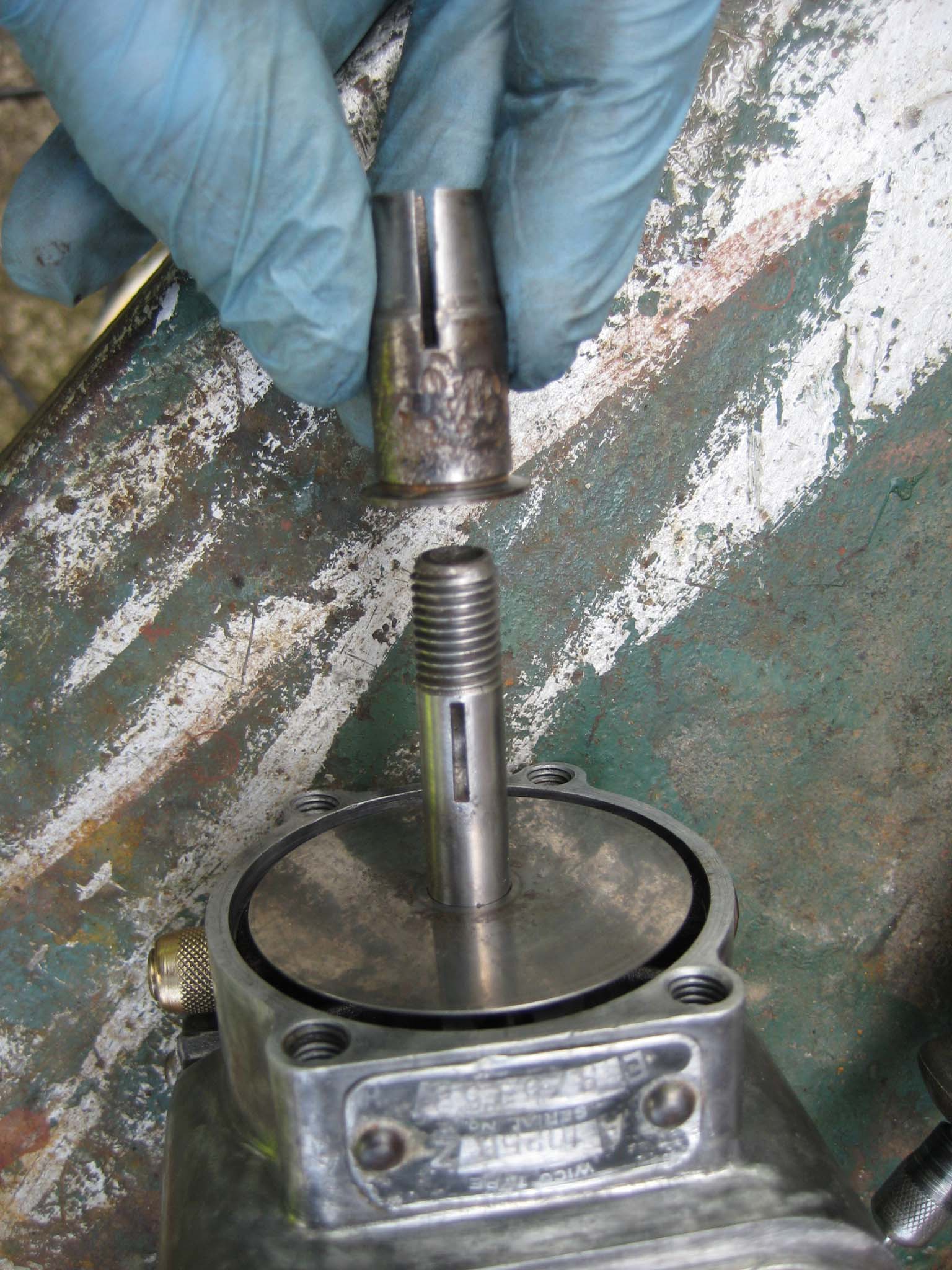
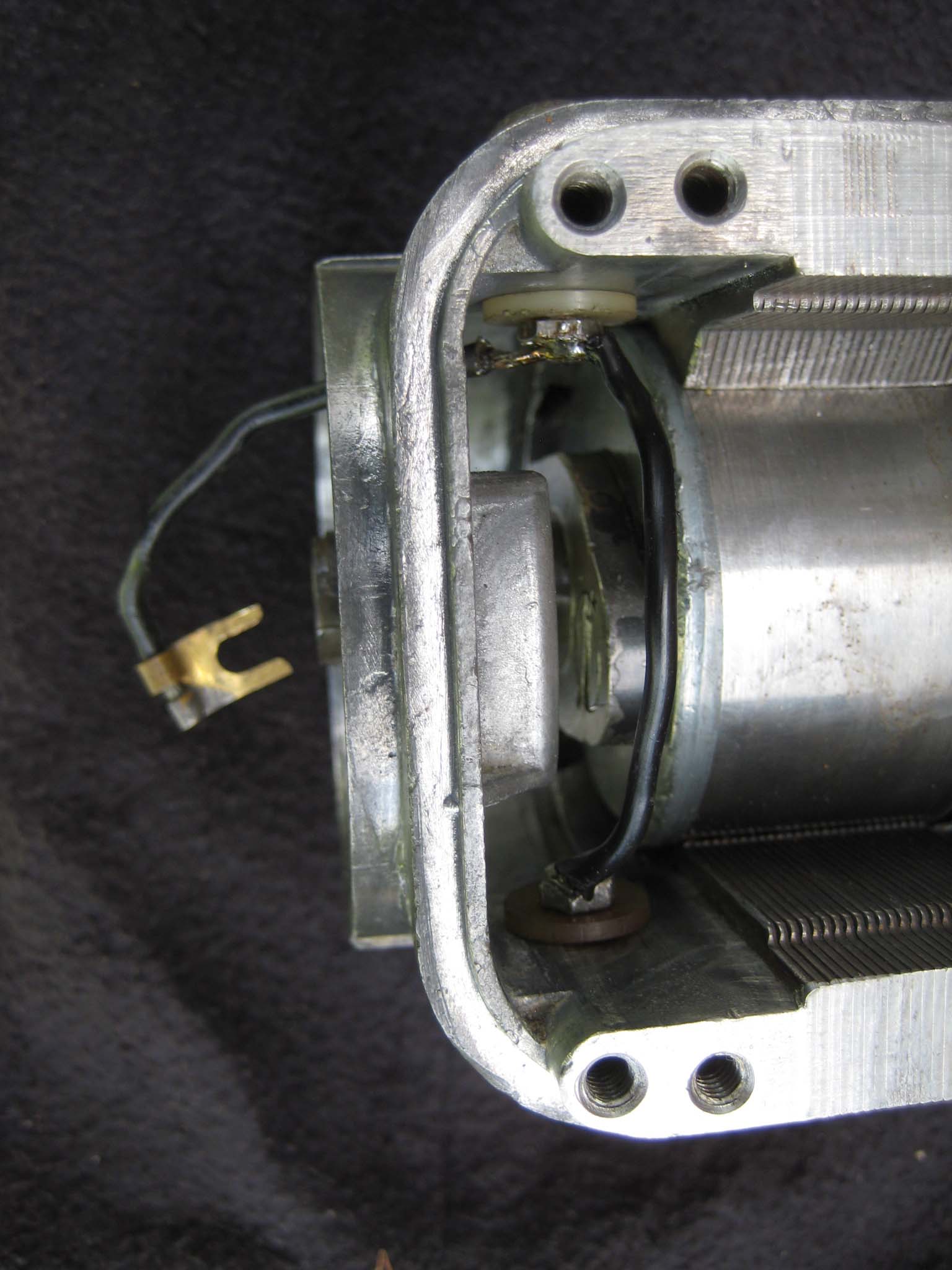
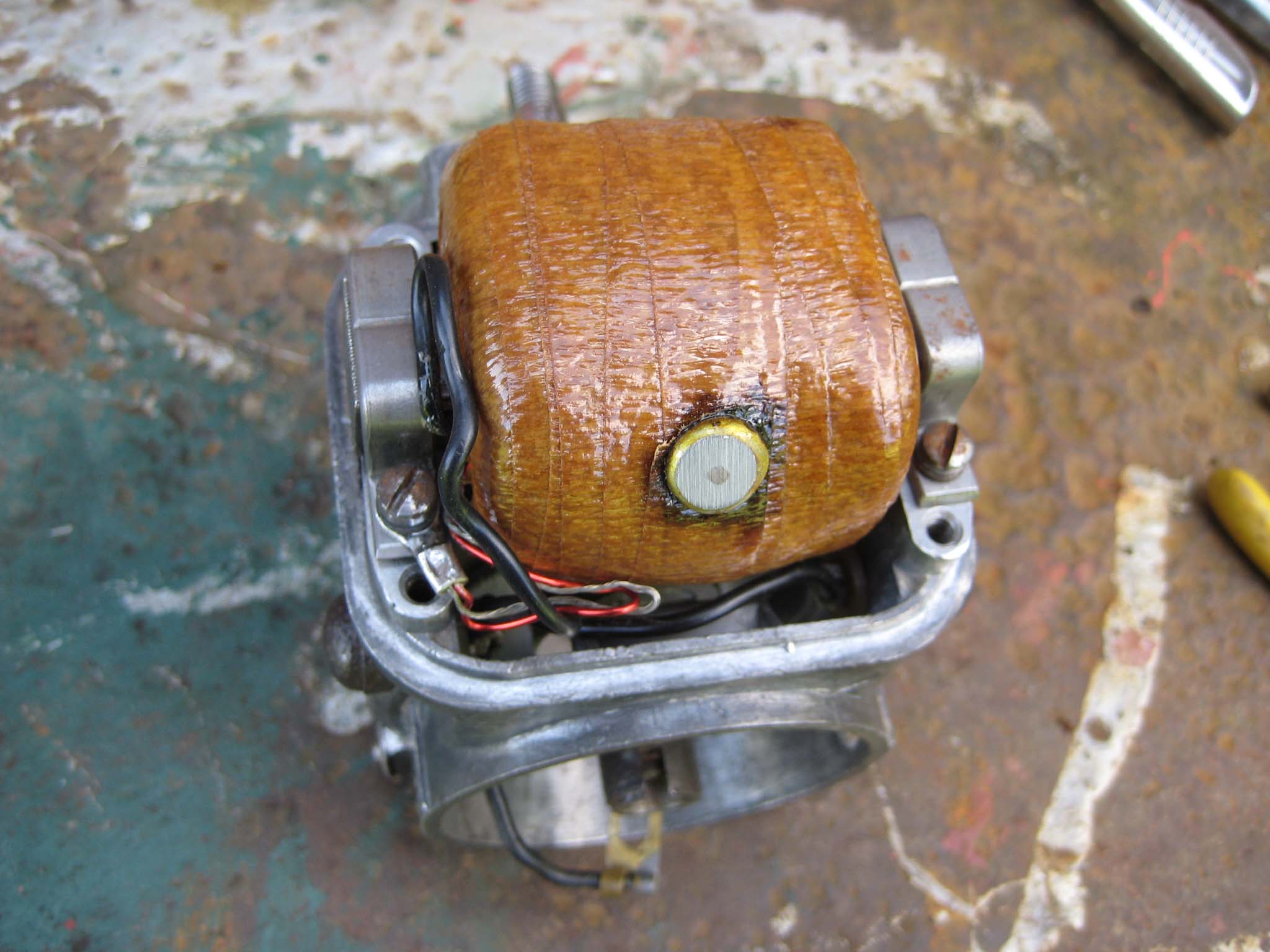
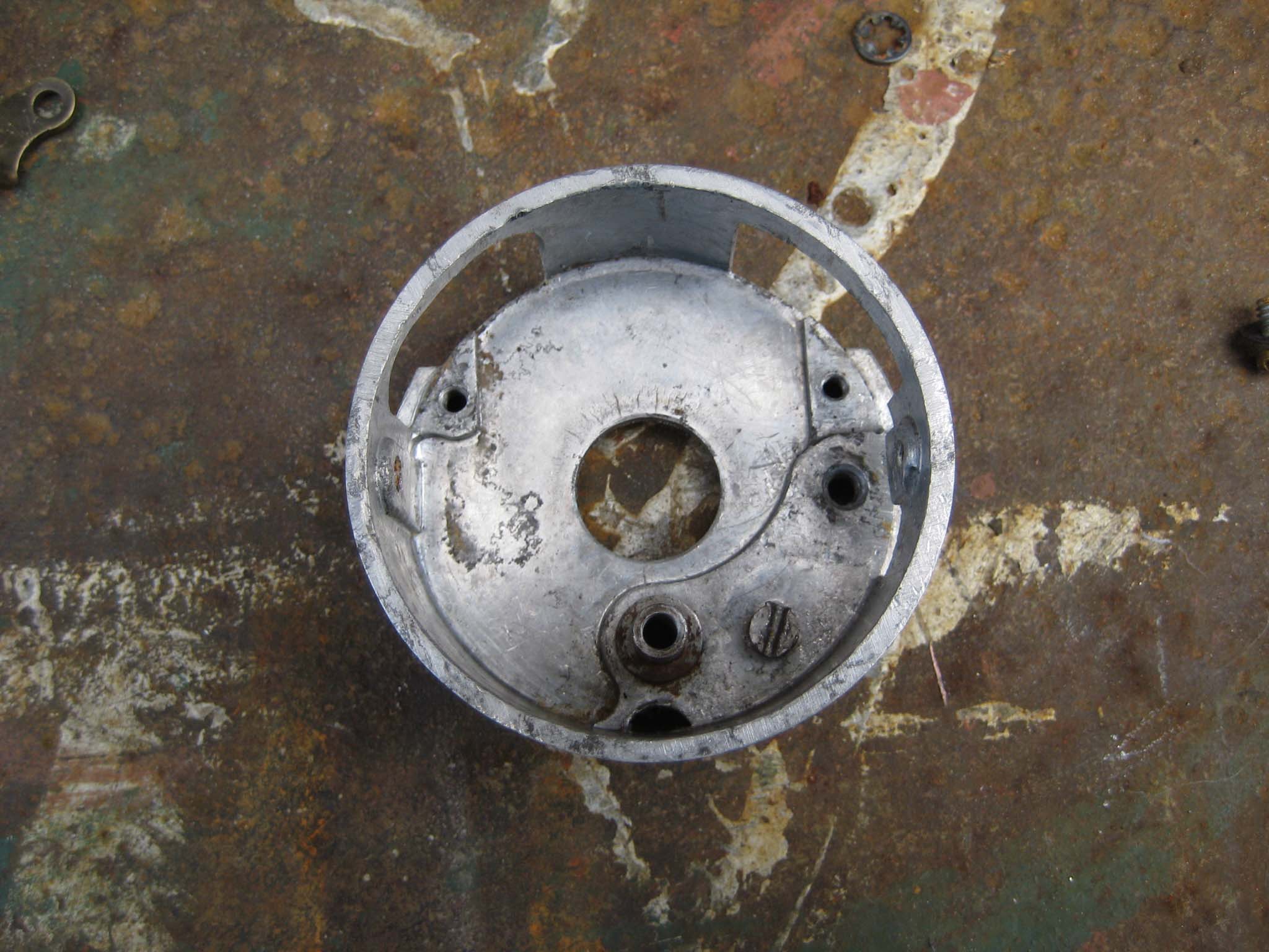
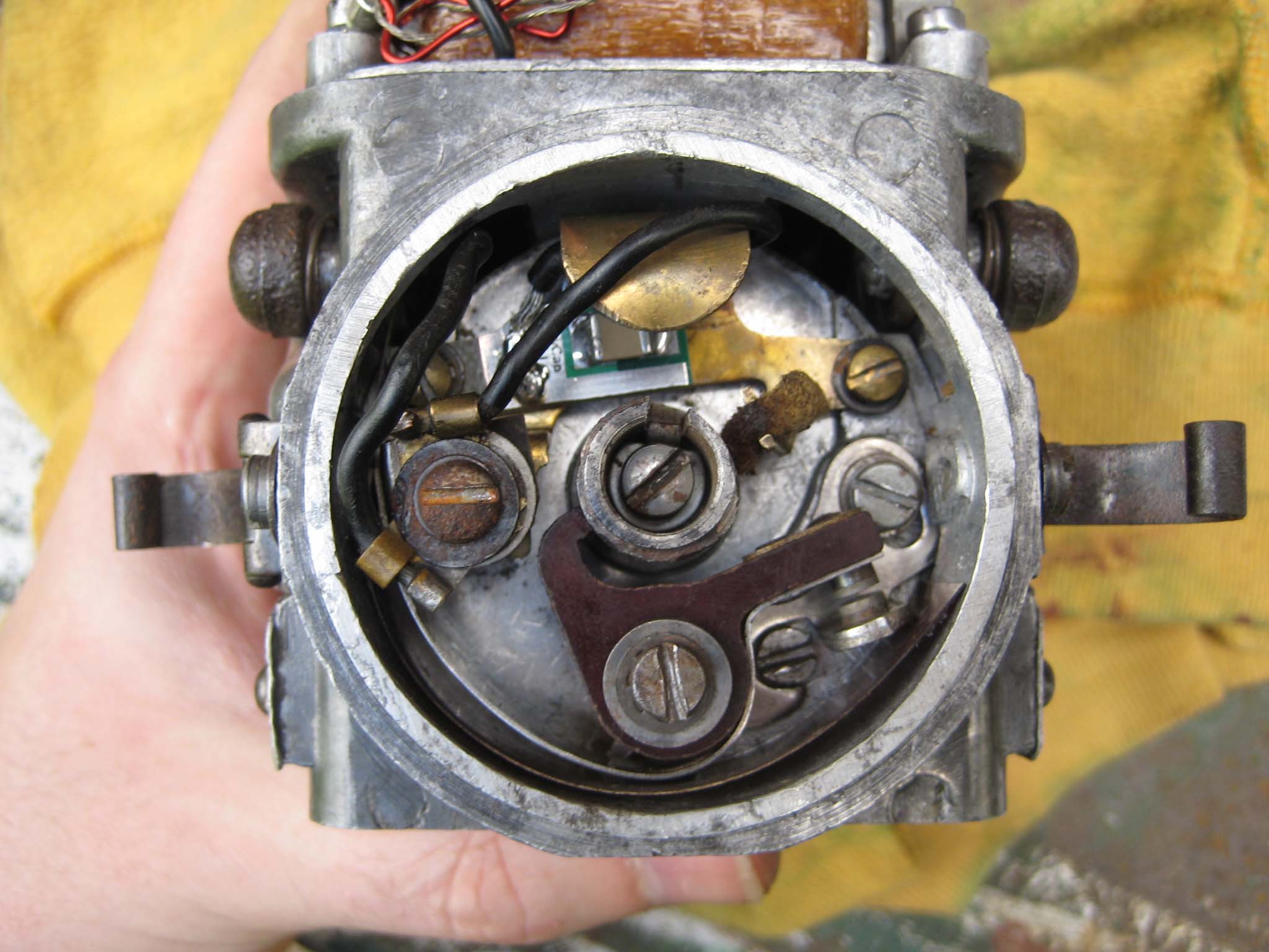
The main housing was cleaned (Mag 0001) in preparation for the rotor (Mag 0002). With the rotor back in the main housing (Mag 0003), the cam which operates the points was attached to the rotor via a half moon key (Mag 0004). The oil pad spring (Mag 0005), oil pad (Mag 0006) and sprung oil scraper assembly (Mag 0007) were fitted. The Brass oilers are a push fit into holes in the main housing (Mag 0008). To complete the lubrication system, the oiling disc was slid over the rotor shaft (Mag 0009). The Simar does not have an impulse coupling on the magneto to aid starting, instead having a tapered collar which is keyed to the rotor shaft (Mag 0010) onto which the drive gear will be installed later. The stop buttons (Mag 0011) were attached to the main housing, making sure not to forget the insulating washers that fit on the inside of the housing (Mag 0012). A new coil was fitted (Mag 0013) before moving on to the points.
Attachments:
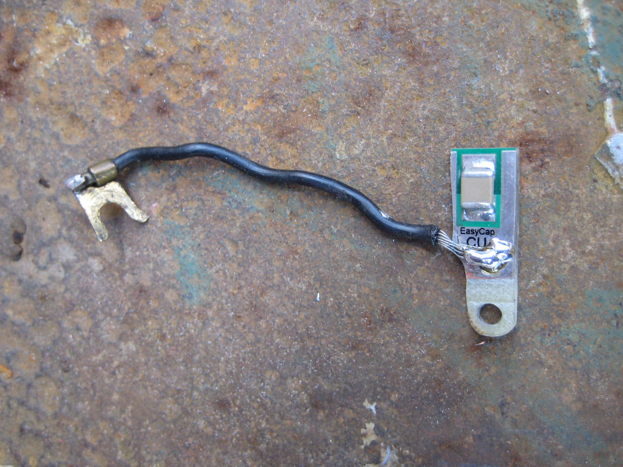
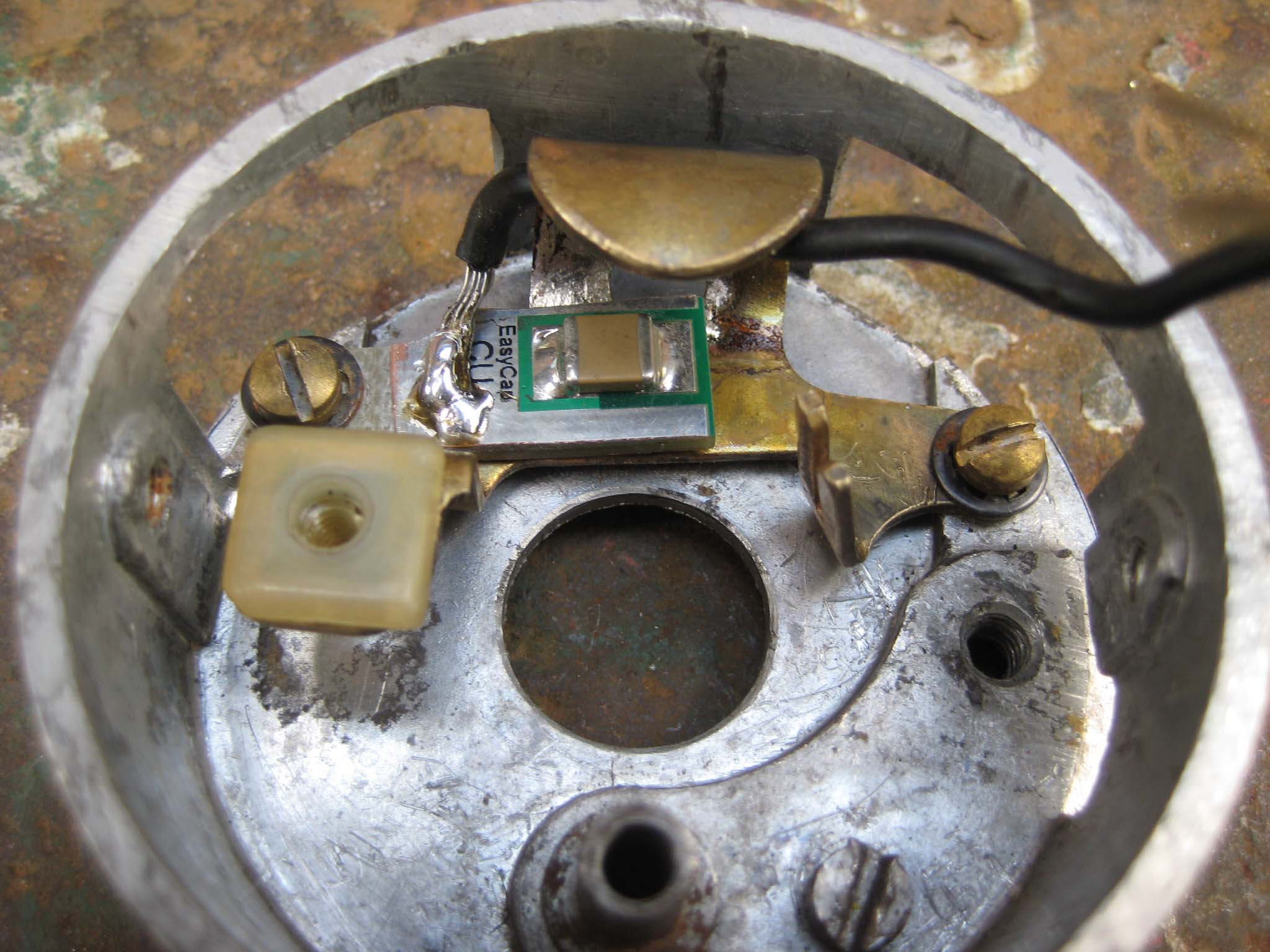
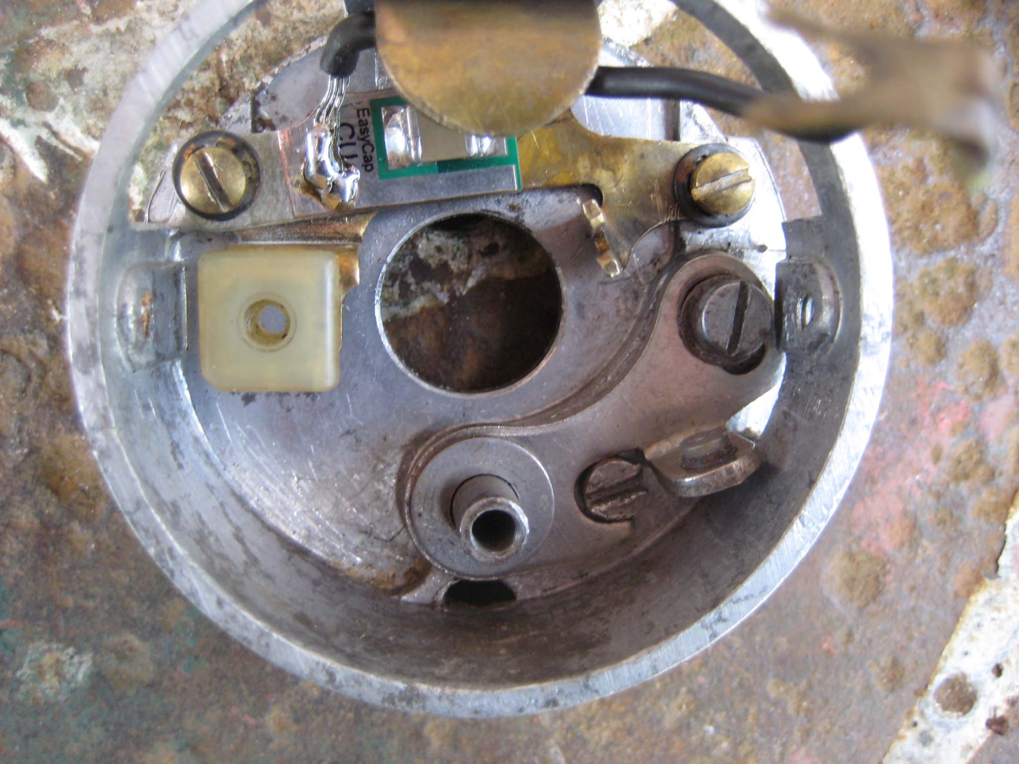
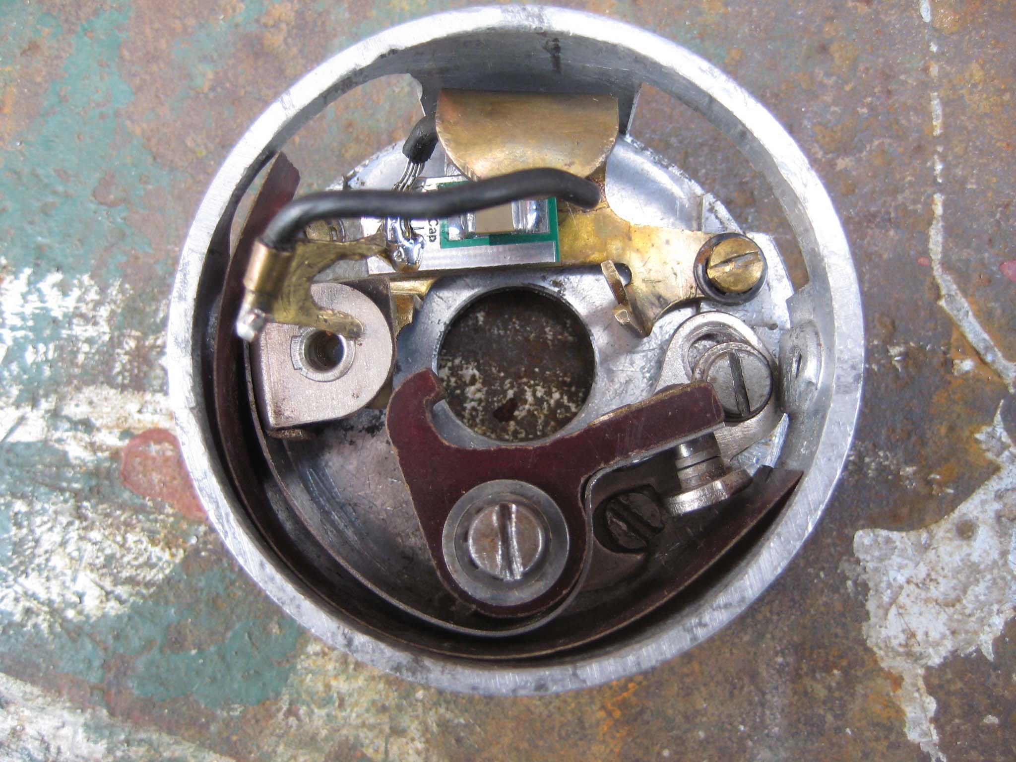
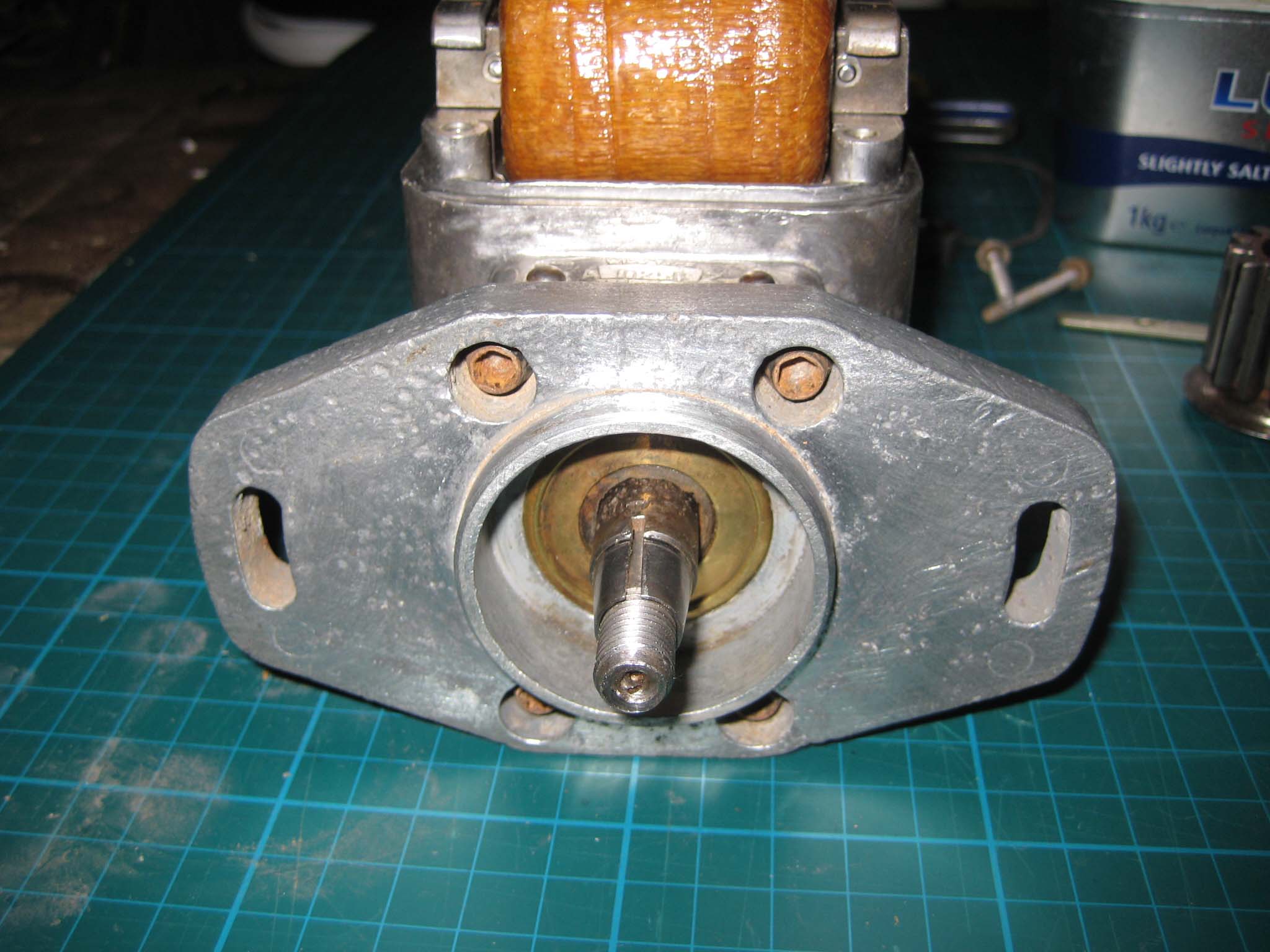
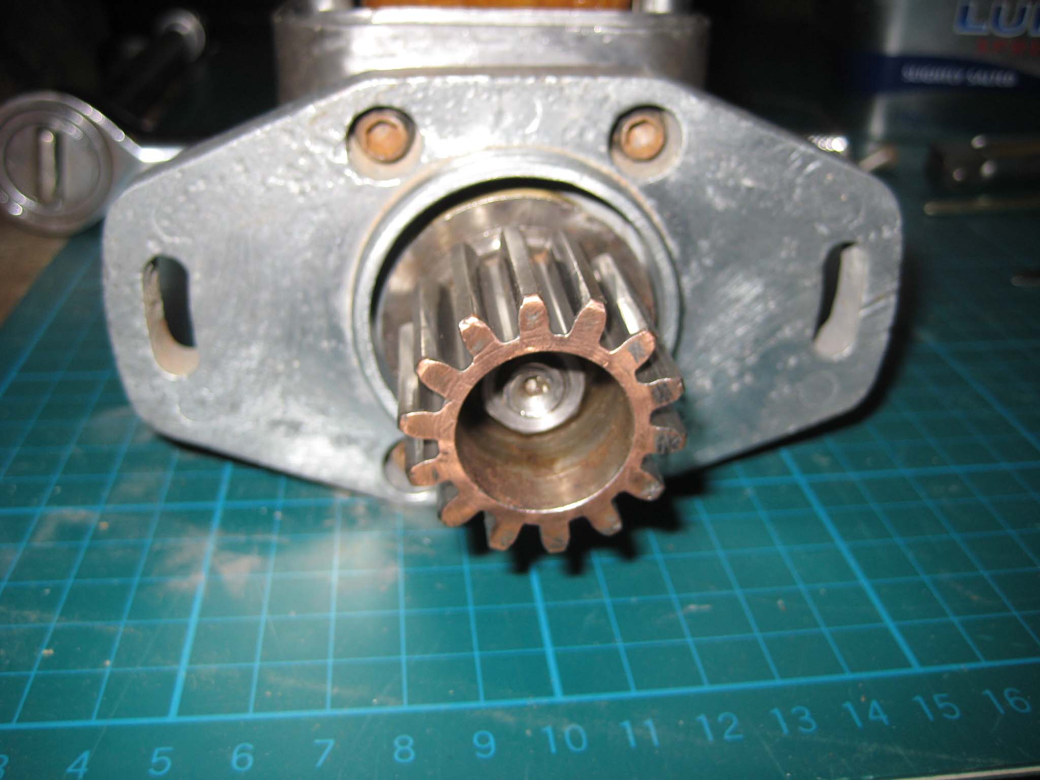
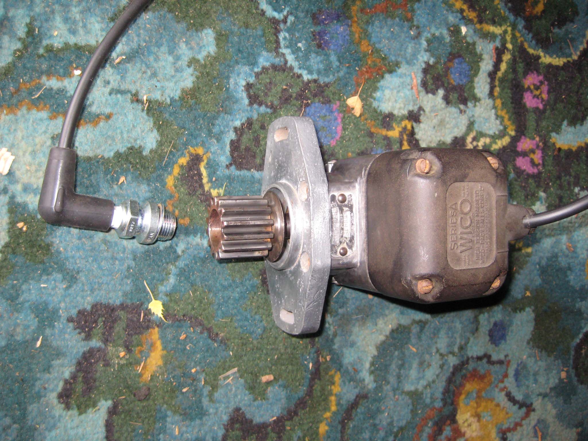
October 24, 2015 at 11:44 am #14969vhgmcbuddyMemberI had already decided that the original condenser would be replaced by an EasyCap condenser from Brightspark Magneto’s. To do this, the original condenser was unsoldered from it’s mounting bracket (Mag 0014). The EasyCap condenser was cut to size so that it would fit onto the condenser mounting bracket and the fly lead soldered in place (Mag 0015). The breaker box was cleaned (Mag 0016) and the condenser and mounting bracket fitted (Mag 0017). The fixed contact went in next (Mag 0018), followed by the breaker arm and strip of insulation around the inside lower half of the breaker box (Mag 0019). The breaker box was then slid back into the main housing, taking care not to trap any wires. The breaker box is clamped into place by the fixing screw which hold the front cover spring clips. The wiring was connected up to the condenser mounting bracket and the felt pad for the cam inserted into the fork in the condenser bracket (Mag 0020). The mounting flange complete with oil seal pressed into the centre was bolted to the main housing (Mag 0021). The drive gear fits on the rotor shaft tapered collar (Mag 0022). The gear is not keyed to the shaft. To complete the job, a new copper HT lead was fitted to the cover along with a NGK AB-6 spark plug (Mag 0023). End result is a fat, Blue spark, even at low speed.
Attachments:
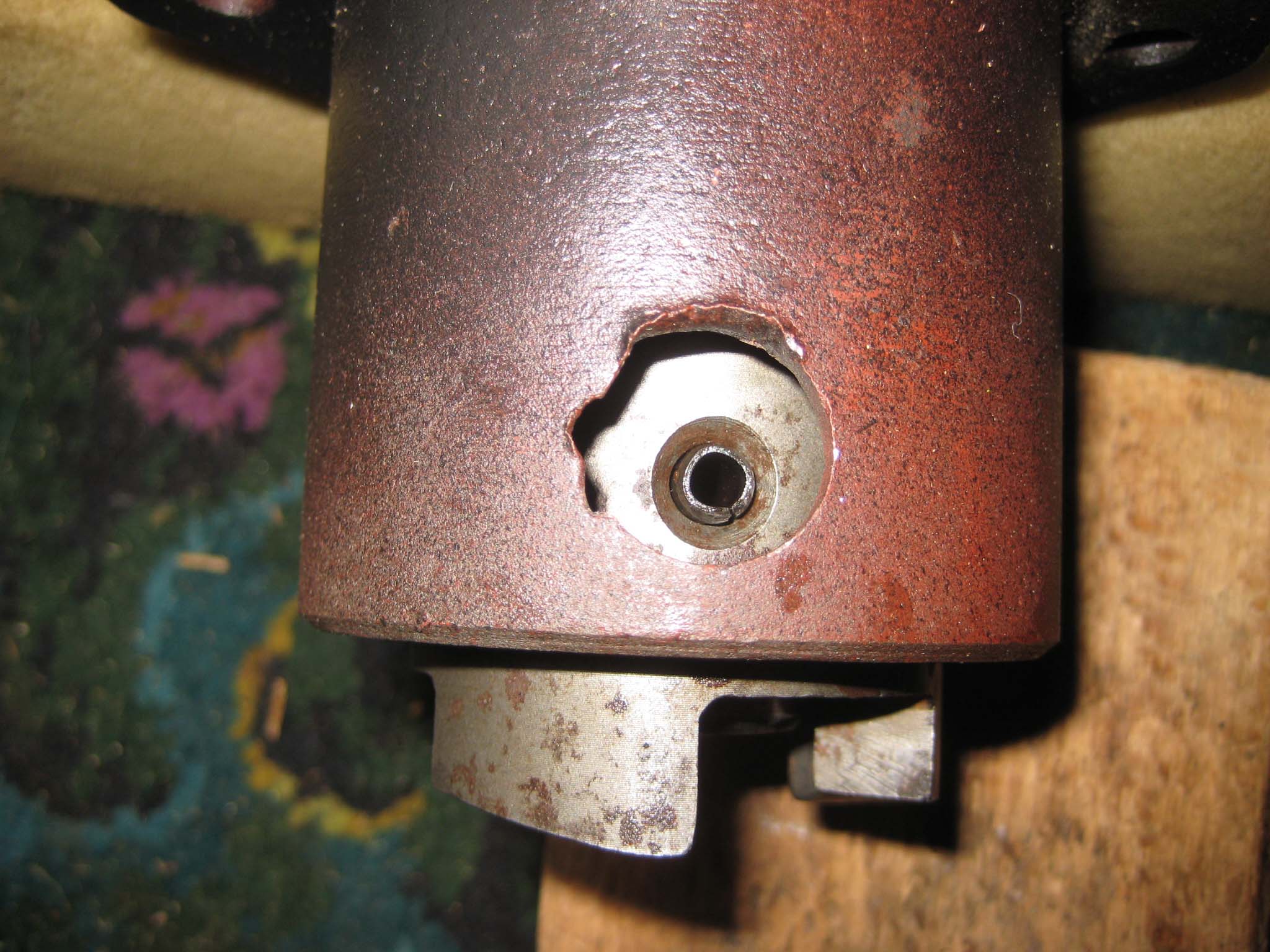
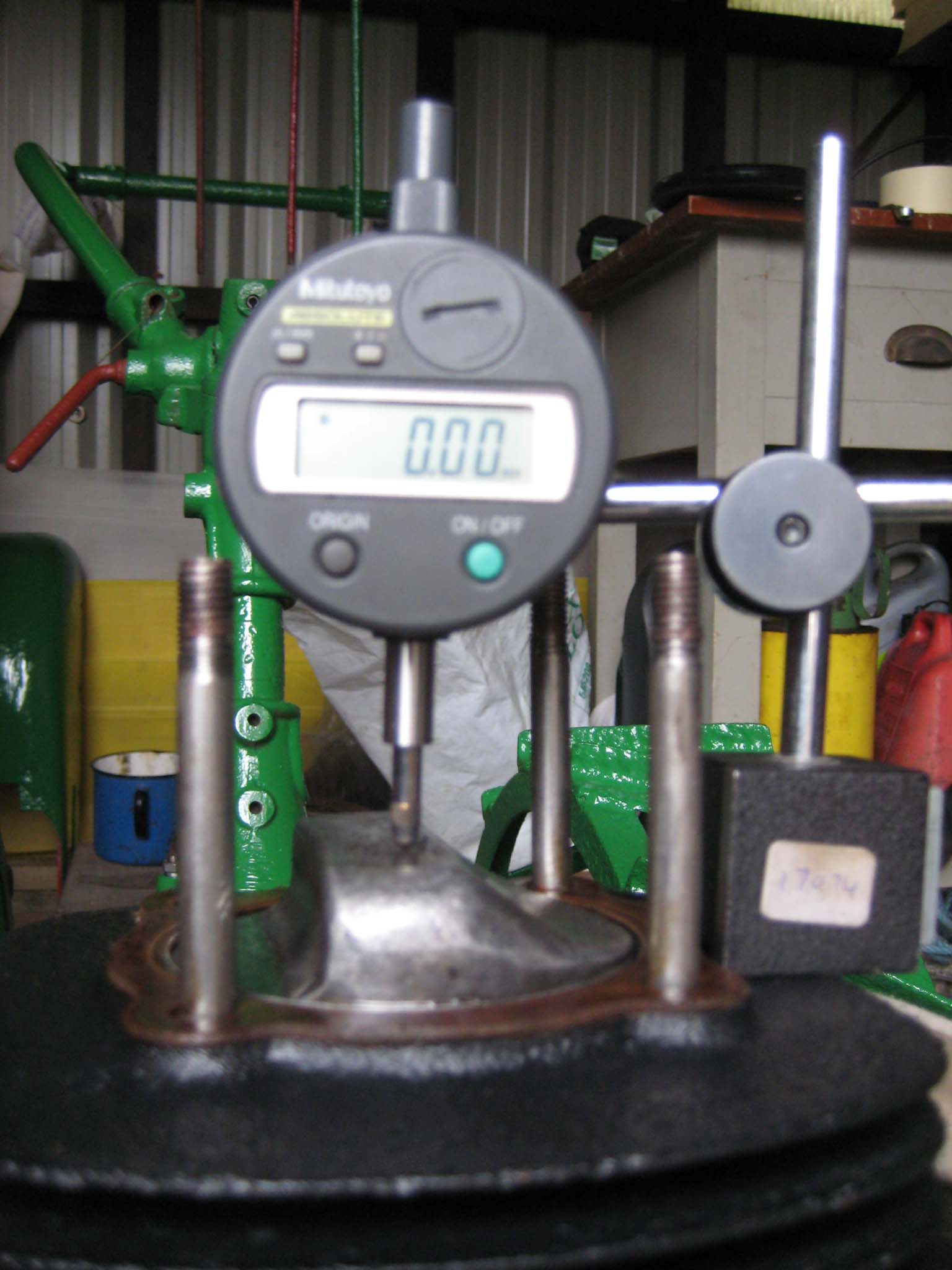
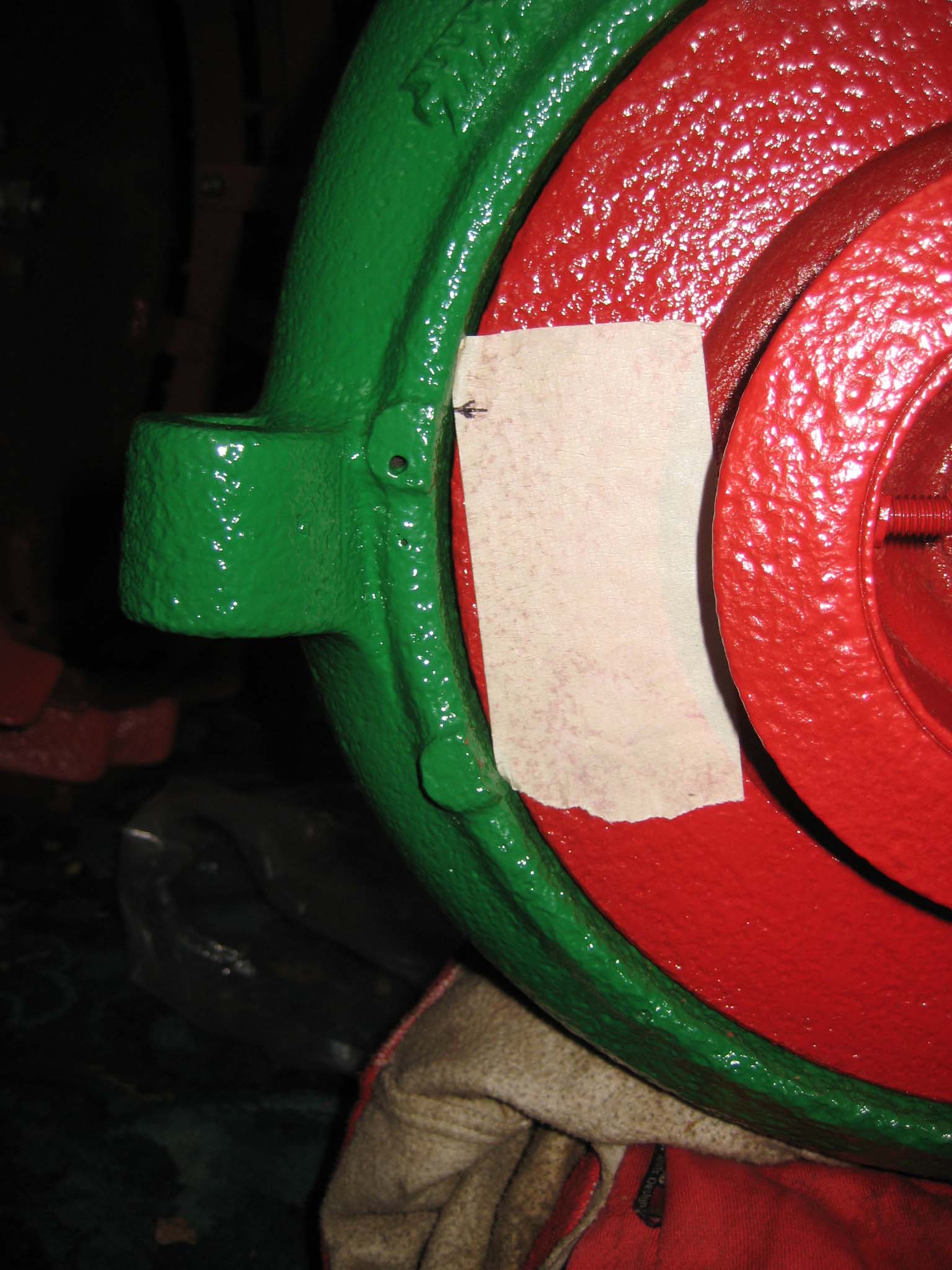
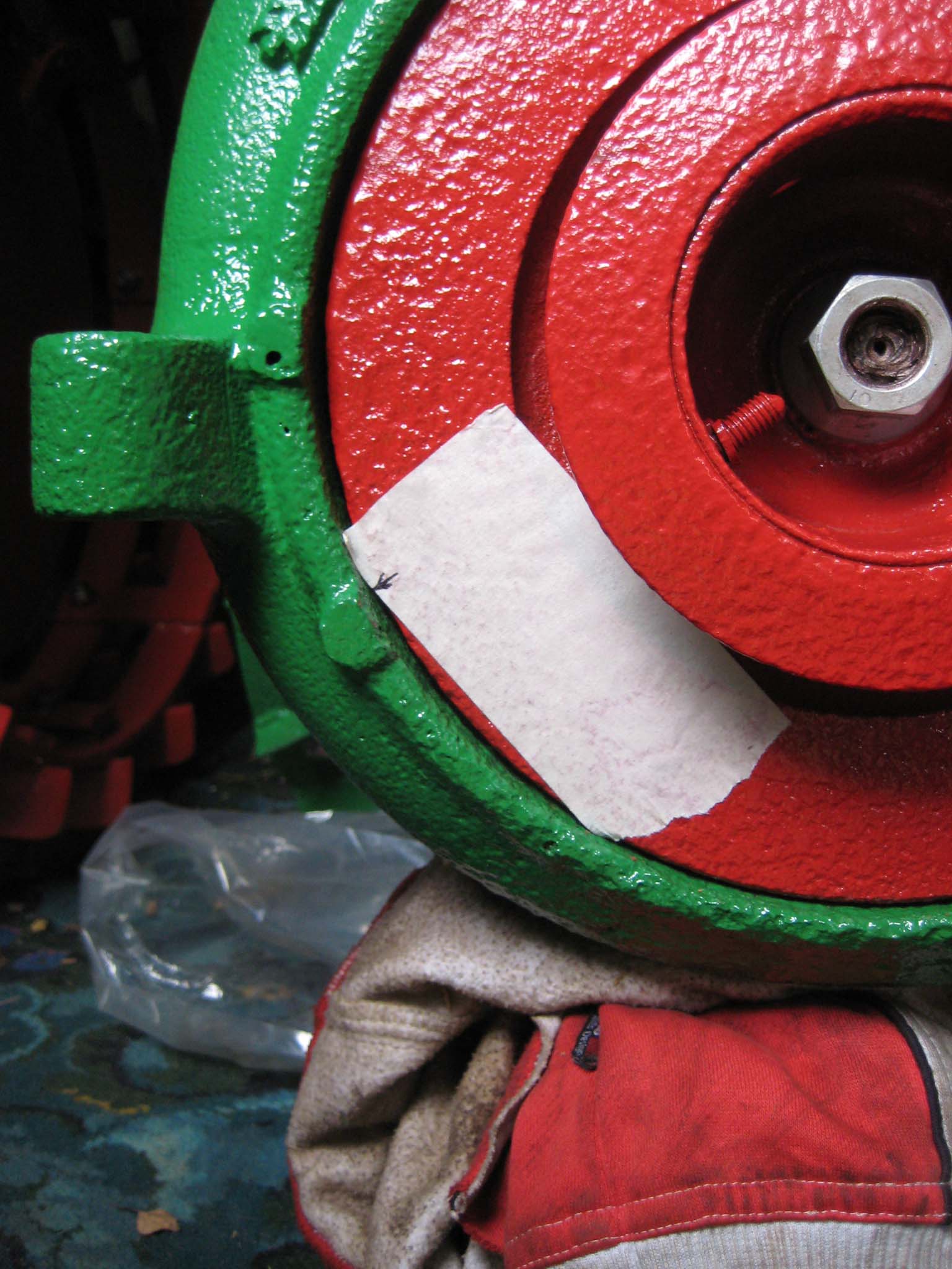
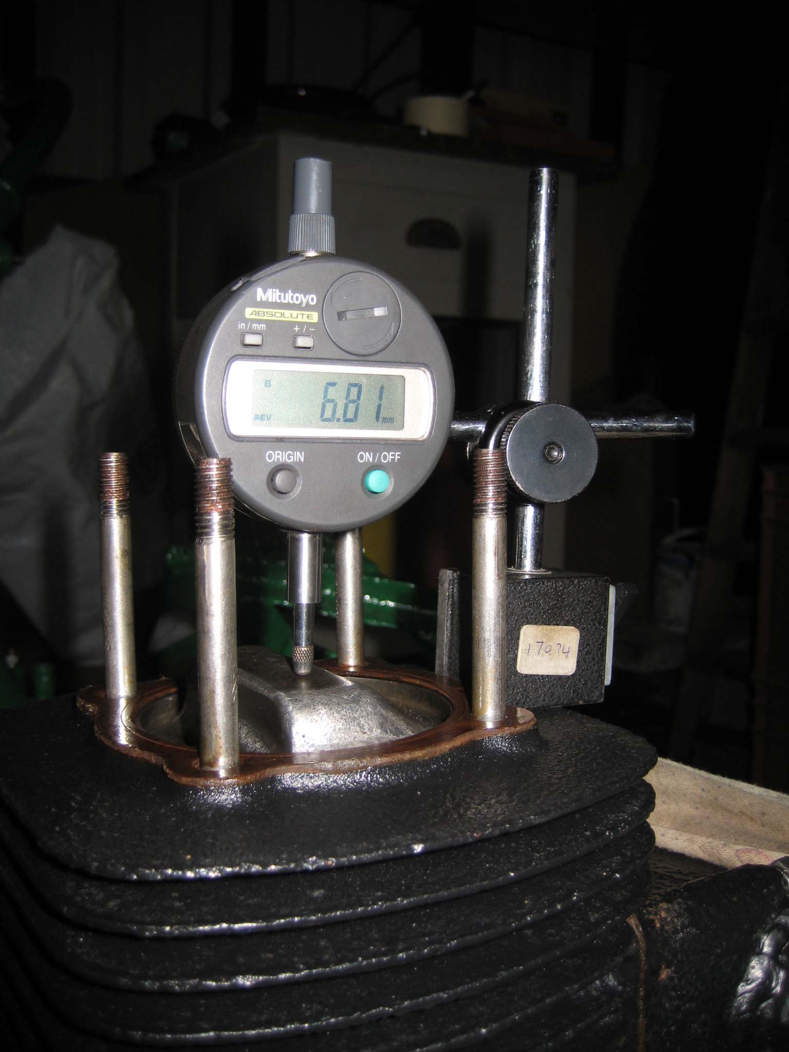
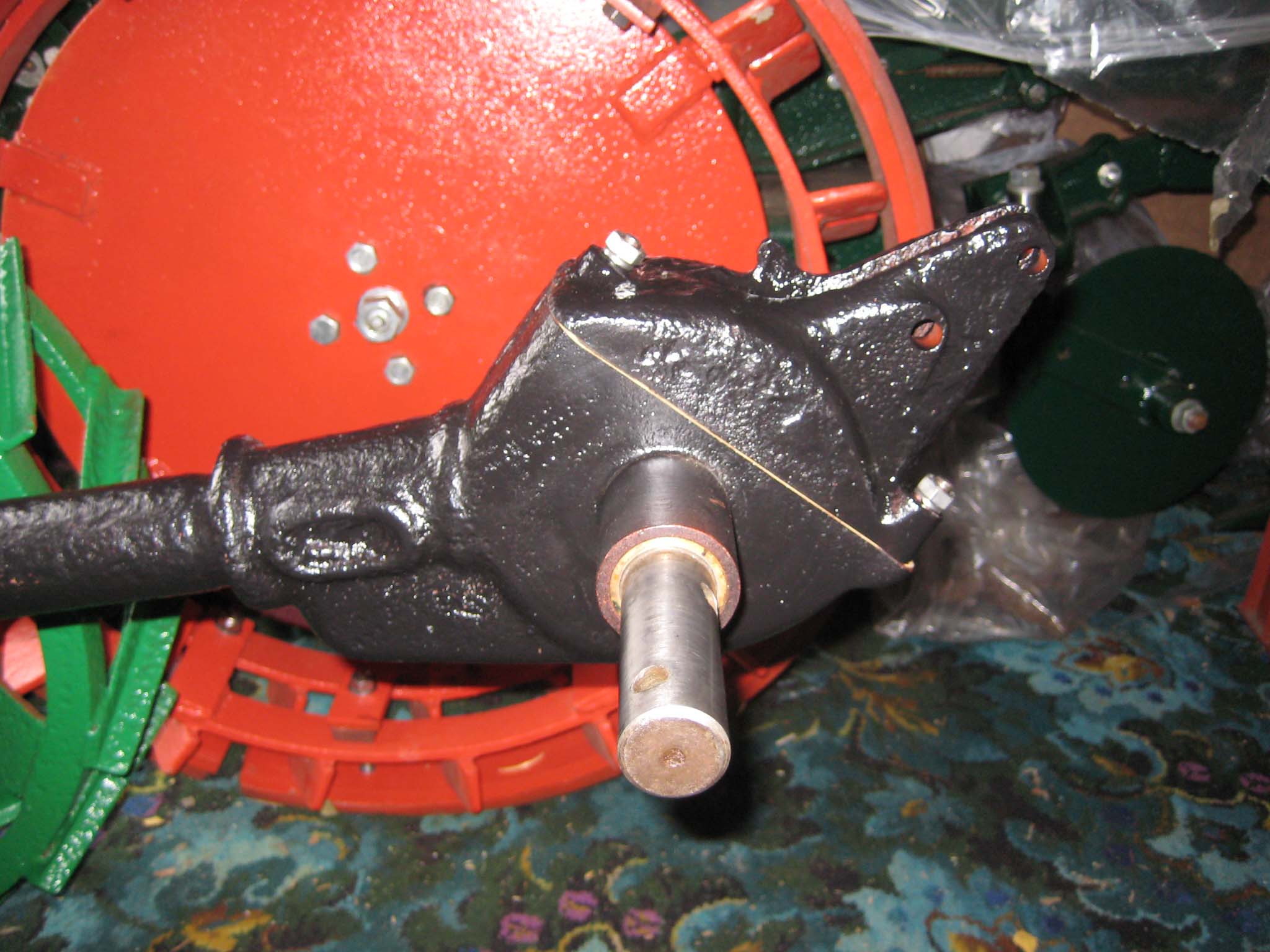
October 24, 2015 at 11:48 am #14980vhgmcbuddyMemberTo refit the magneto, I first needed to ensure that the piston was positioned at the point the magneto contact breaker would begin to open. I removed the cylinder head so I could use a dial test indicator to establish top dead centre (Simar 0092). I then marked the cooling fan adjacent to a lump on the right of the fan casing (Simar 0093). The fan was rotated anti-clockwise until the mark lined up with another lump on the fan casing (Simar 0094). The amount rotated was 68mm measured around the circumference of the fan. The reading on the dial test indicator showed that the piston had dropped by 6.8mm (Simar 0095), a factor of 10 less than the distance measured around the fan circumference. Coincidence or clever design?
I set the magneto up with the points just starting to open and then bolted it to the main gearbox (Simar 0096). The mounting plate on the magneto has slotted holes, so fine tuning of the timing can be done by slackening the bolts and rotating the magneto.Attachments:
November 7, 2015 at 12:58 pm #15082vhgmcbuddyMemberA new paper gasket was made for the miller gearbox cover and fitted along with the three M8 studs and two locating pins for the miller shaft bronze bushes (Simar 0097), after which the miller gearbox cover was fitted (Simar 0098). Moving back around to the front of the machine, three M8 studs were screwed into the fan casing (Simar 0099) and the engine cowling installed (Simar 0100). Next to be fitted was the reverse motion clutch lever. The lever is held on the shaft by a 5 x 26mm tapered dowel pin (Simar 0101). If removing any of the three clutch levers, it is important that you establish which end of the pin is the larger diameter, so the pin can be driven out in the correct direction i.e. from the smaller end.
Attachments:
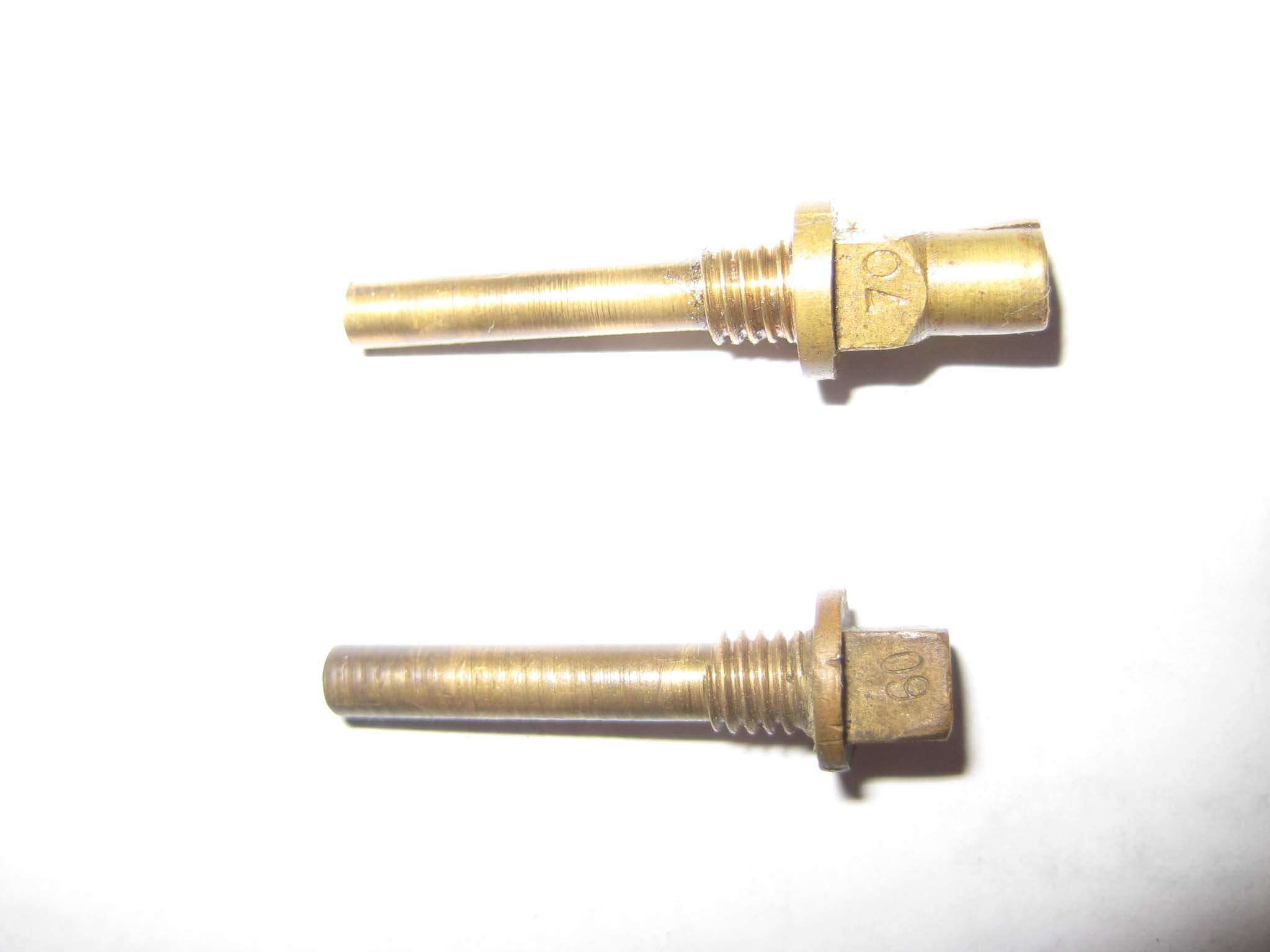
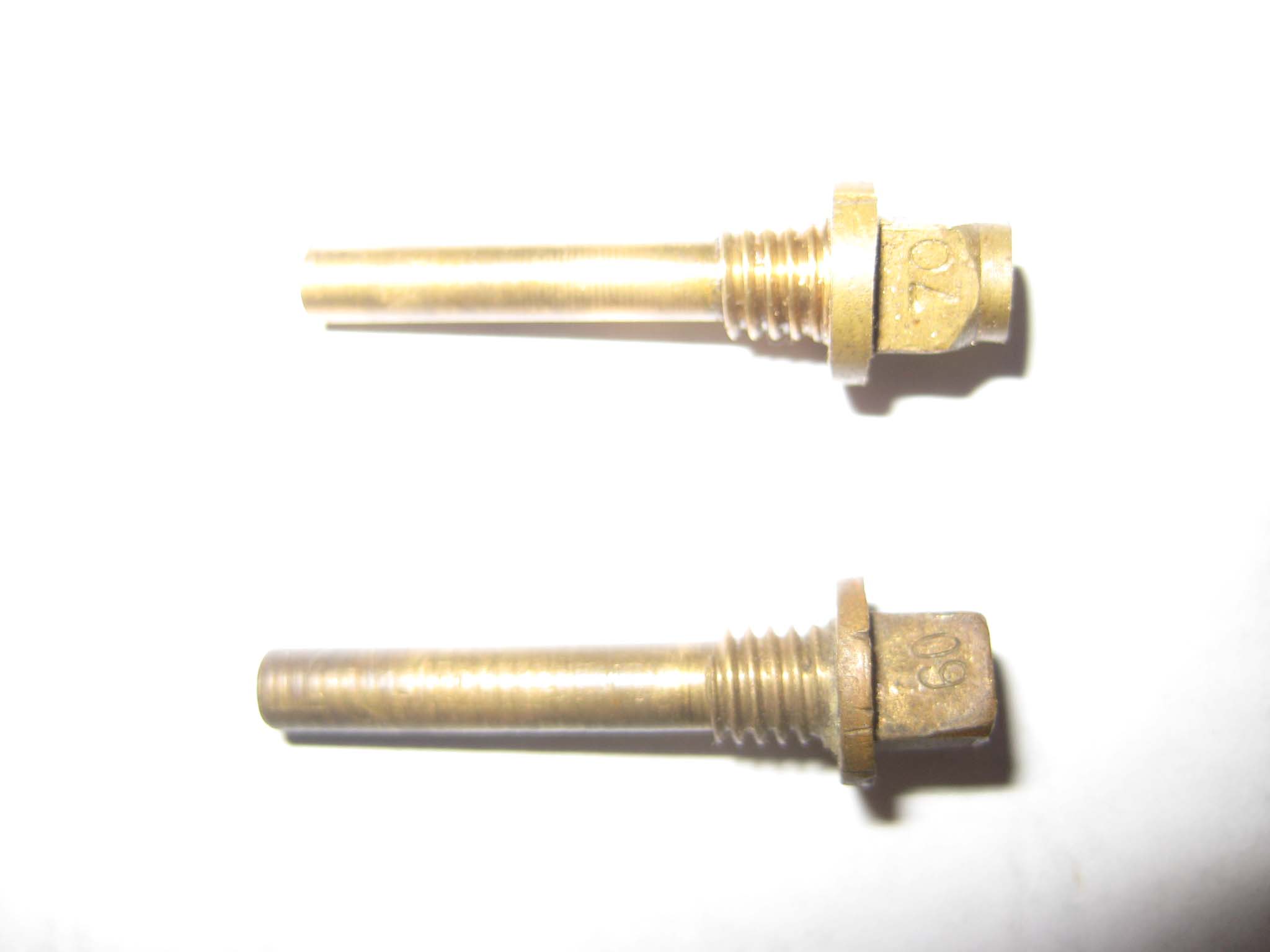
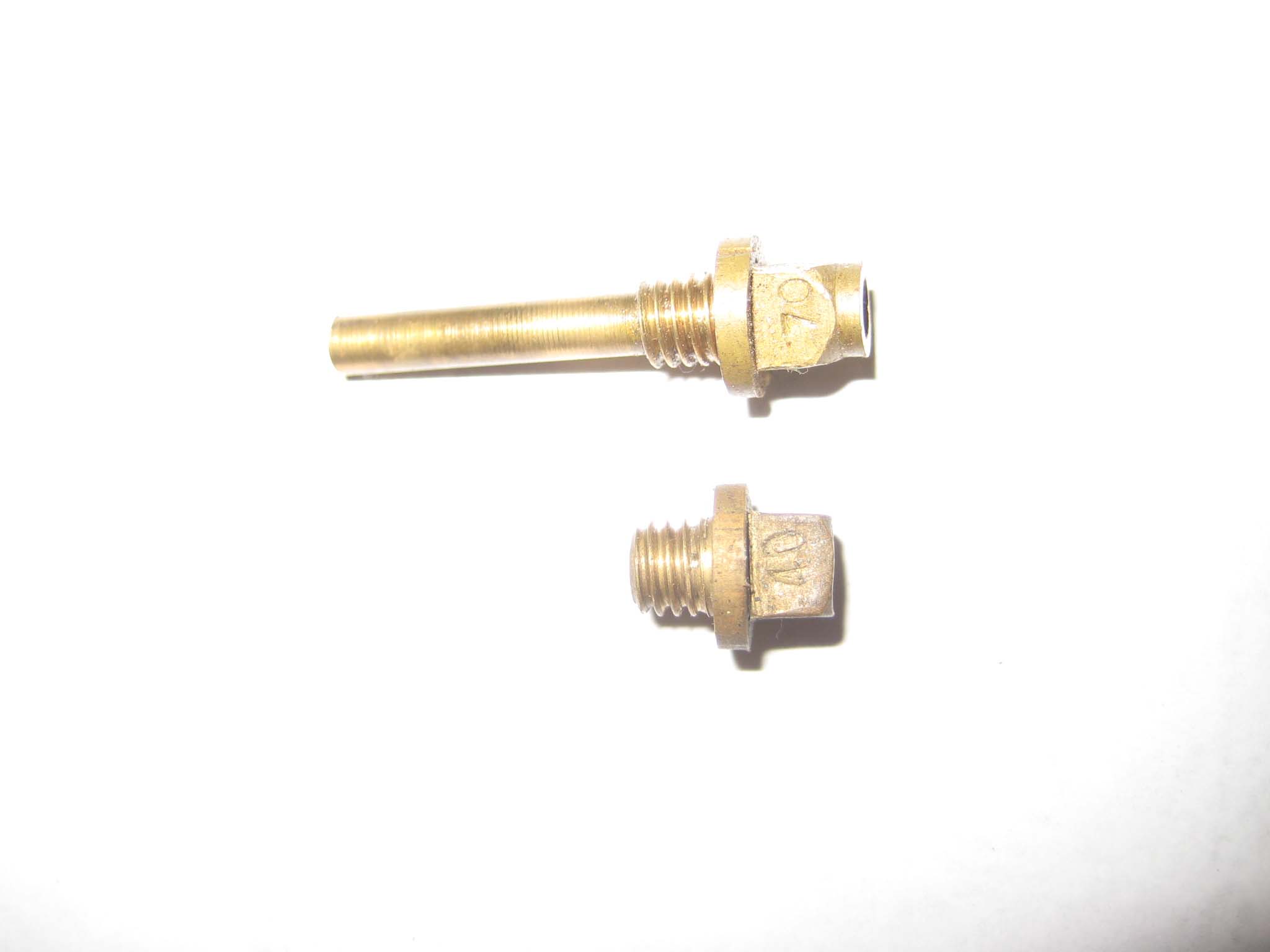
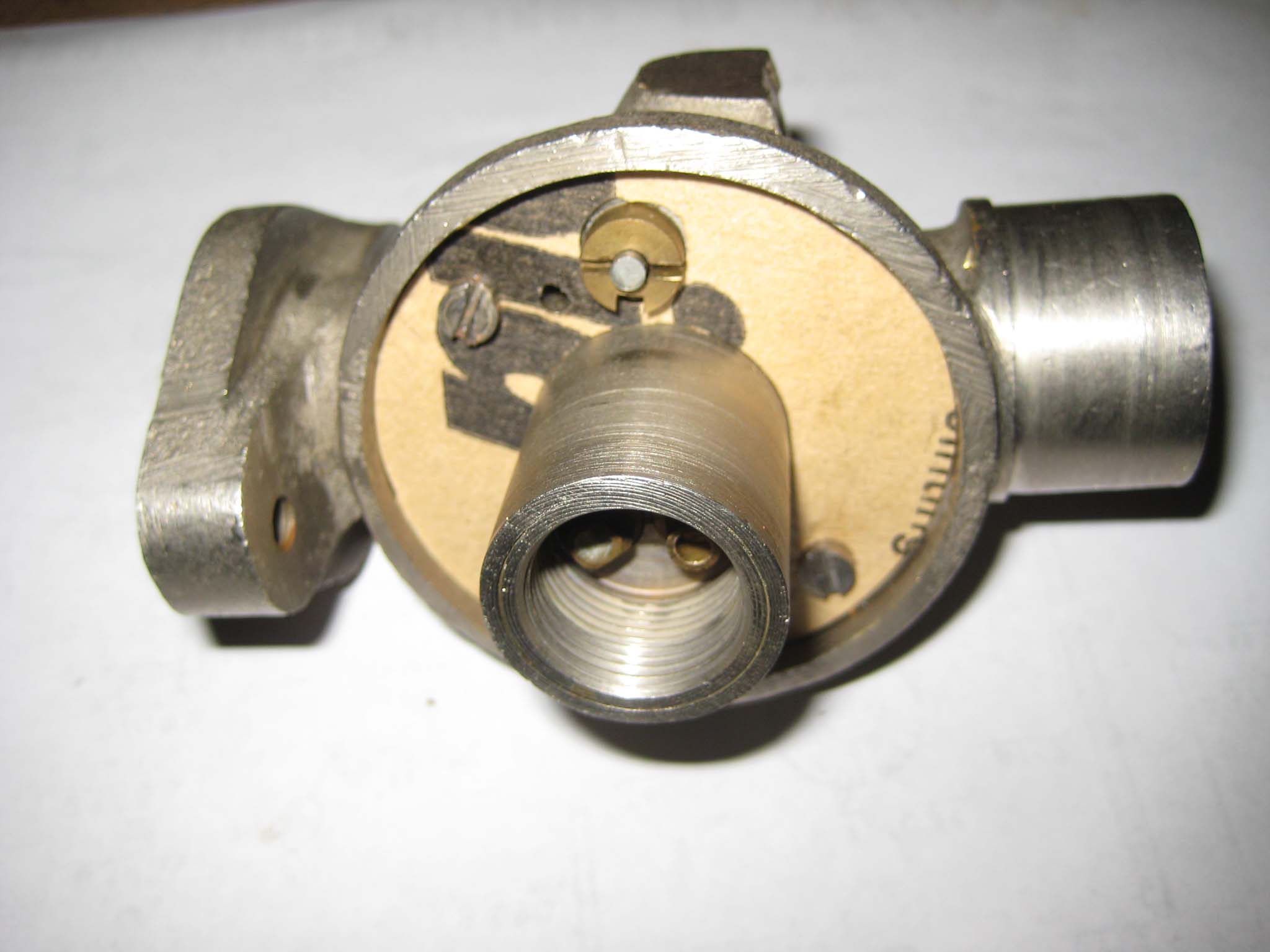
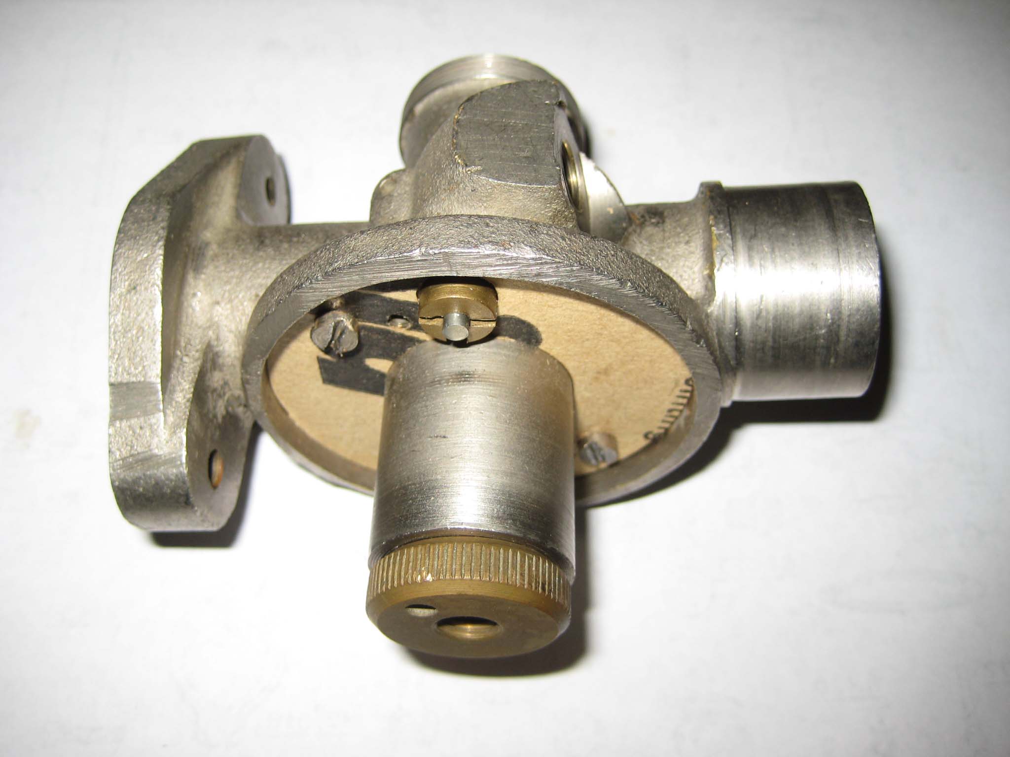
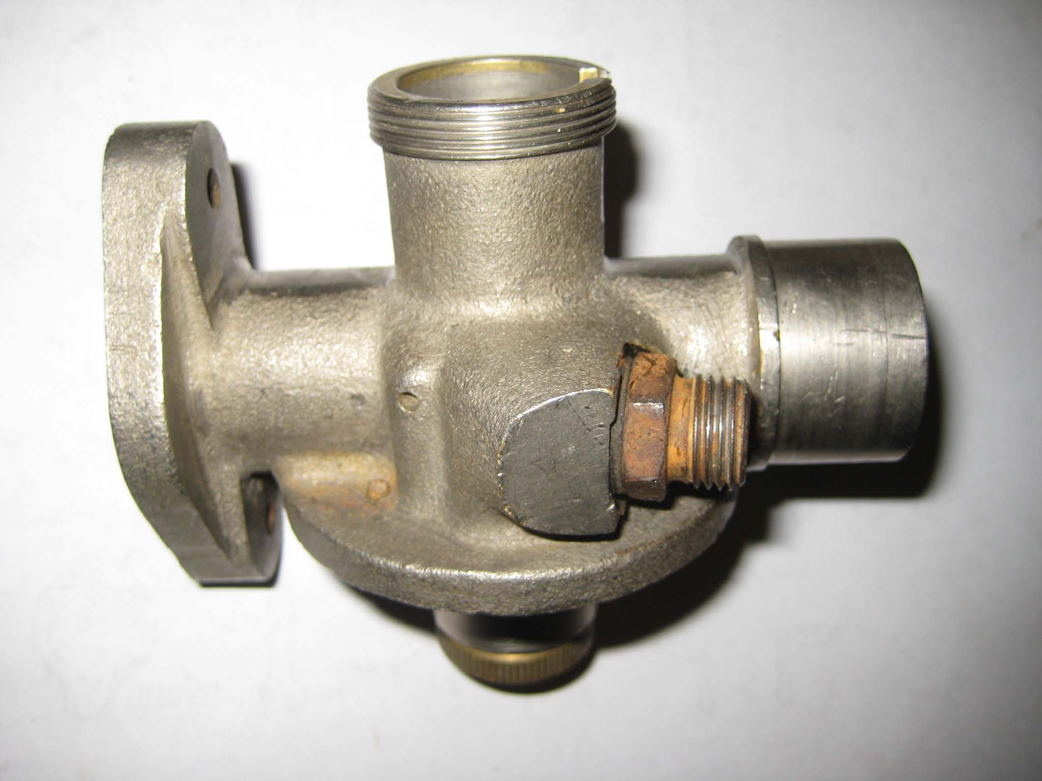
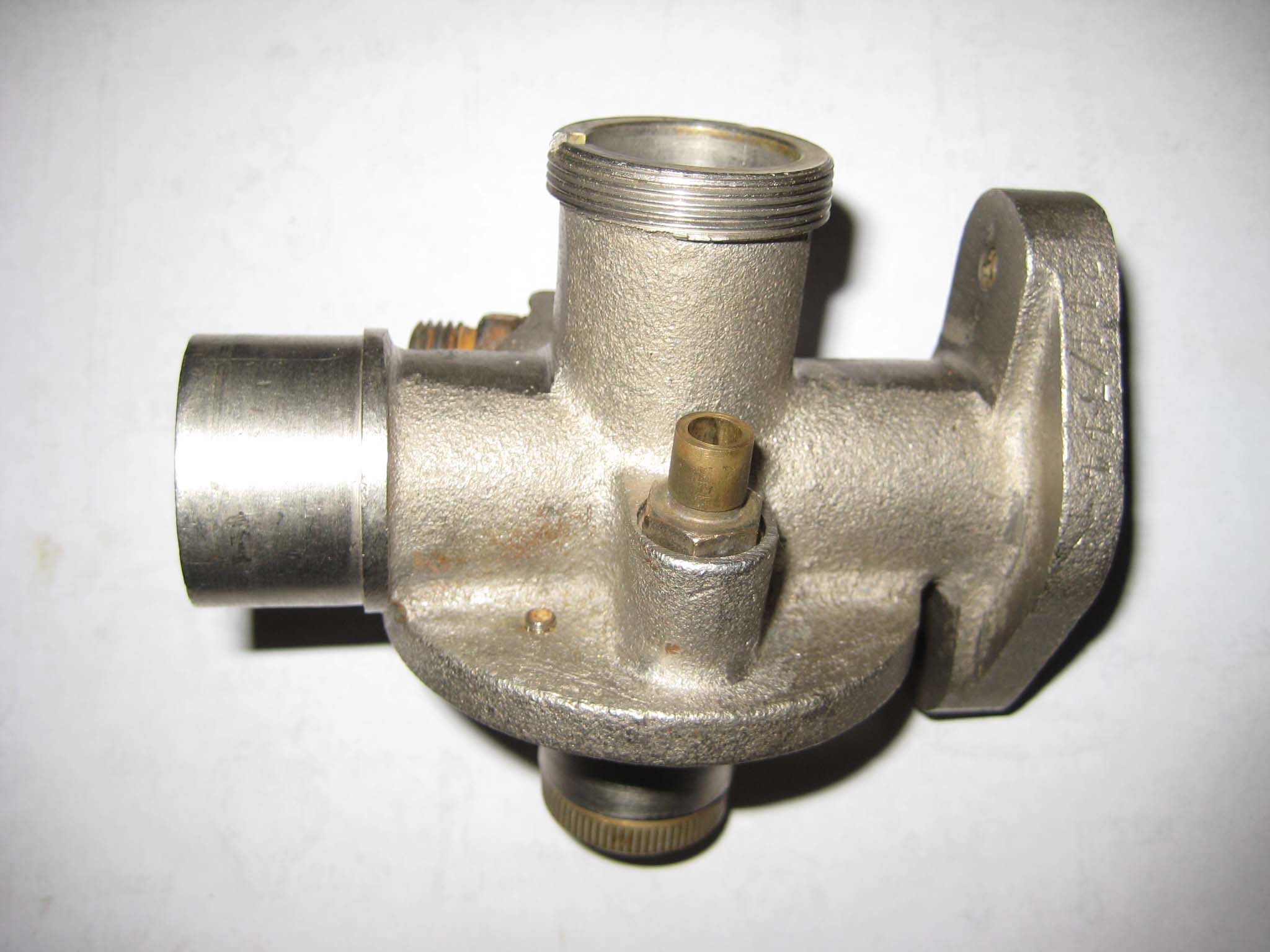
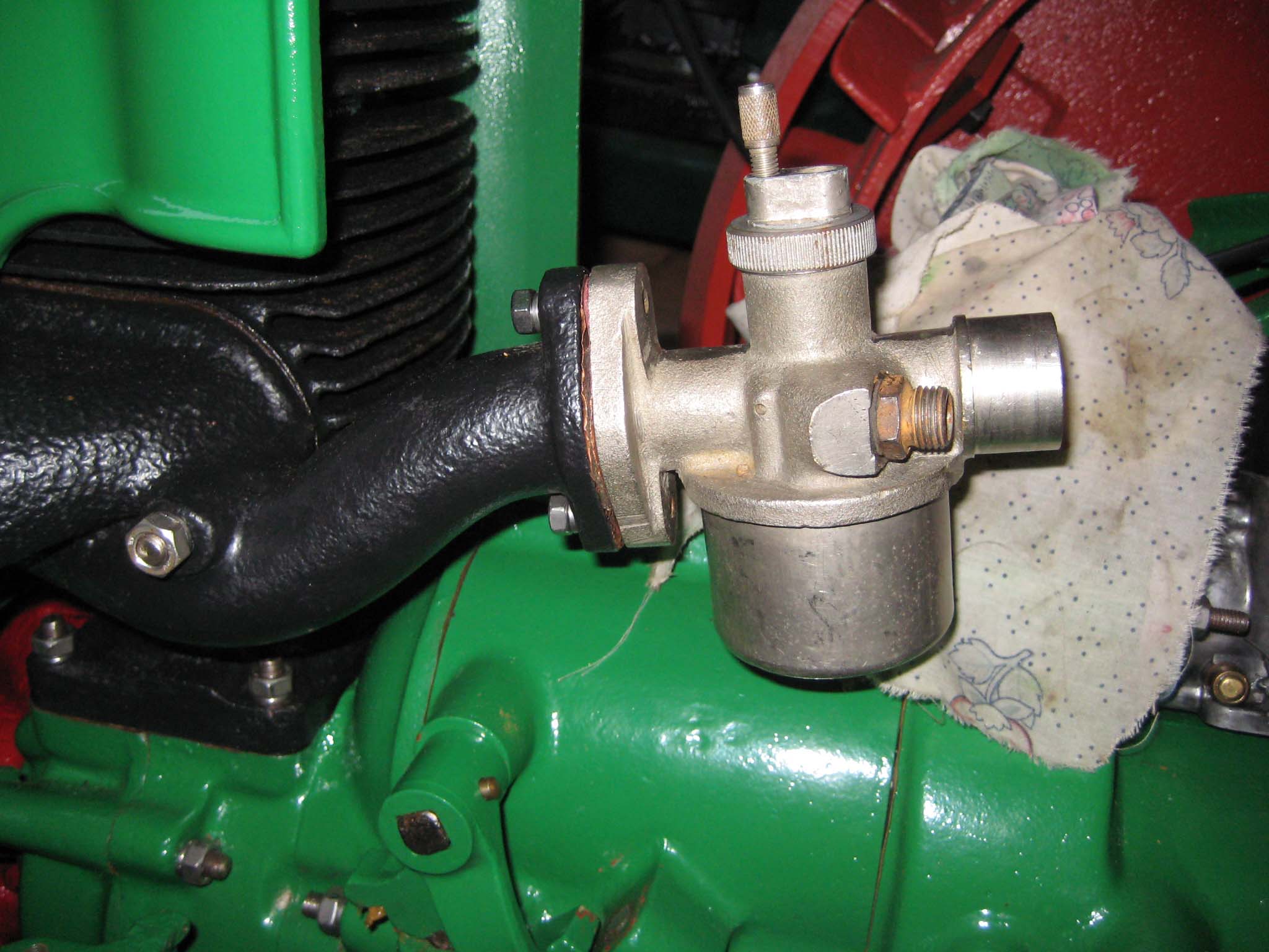
November 7, 2015 at 1:05 pm #15088vhgmcbuddyMemberI next focused my attention on the carburettor. At some point in the machines past, it had lost it’s original carburettor, having been fitted with an Amal 348/7. Charlie was able to provide me with the correct model number, this being an Amal 244/544. With this information, I was able to quickly track one down at a classic motorcycle spares seller in the north of England, although on dismantling this carb, I found that the main jet had been damaged by over tightening of the float bowl fixing bolt. So, the hunt was on for another, which after several months was found on that well known auction site. The item was indicated as being for a Simar 56, but using information posted on this forum, the size of the jets would suggest it was actually from a Simar 35, as the main jet was a size 60 instead of a size 70. This carb was also found to be missing it’s float, so I decided to use the first carb purchased.
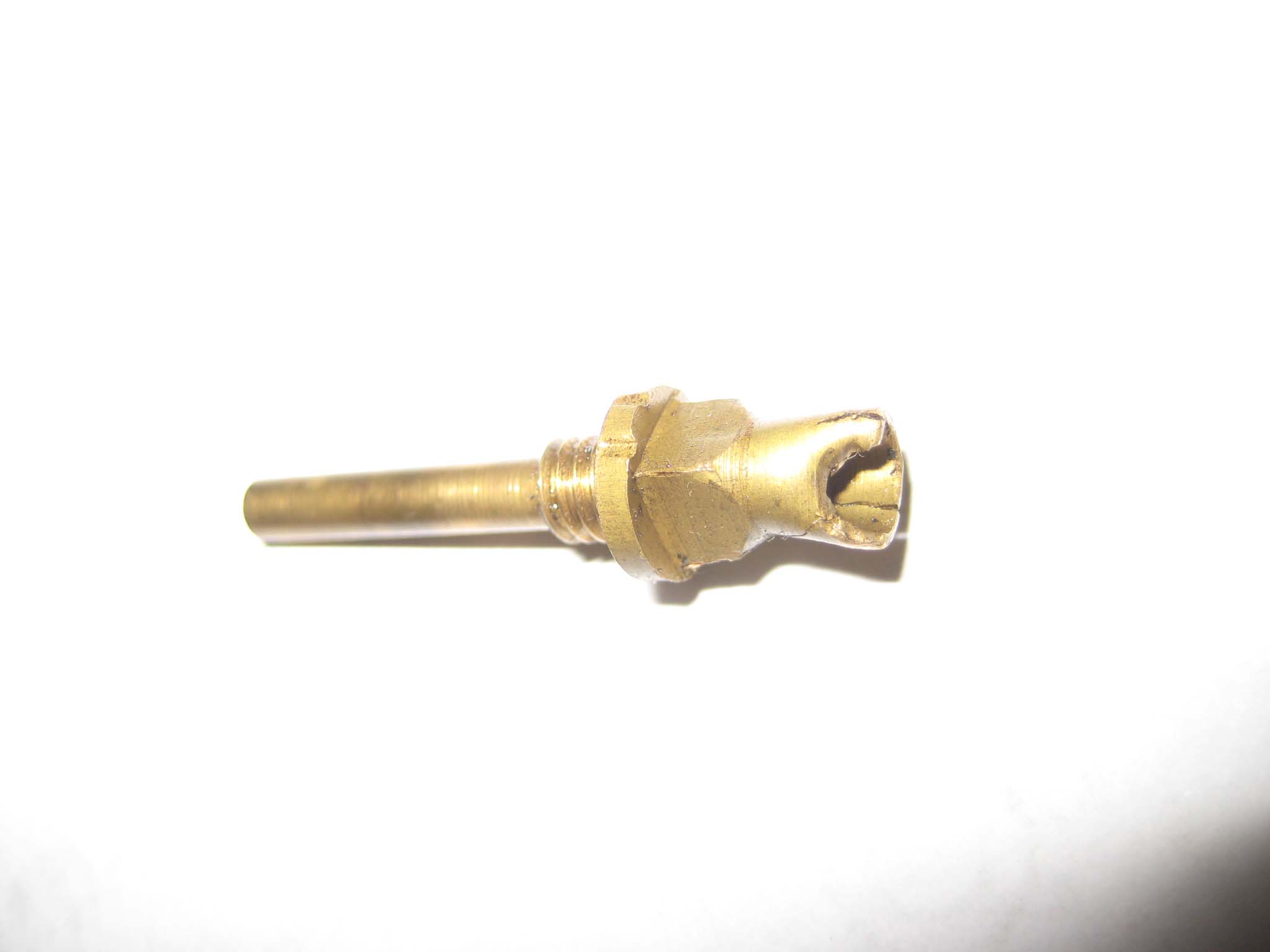
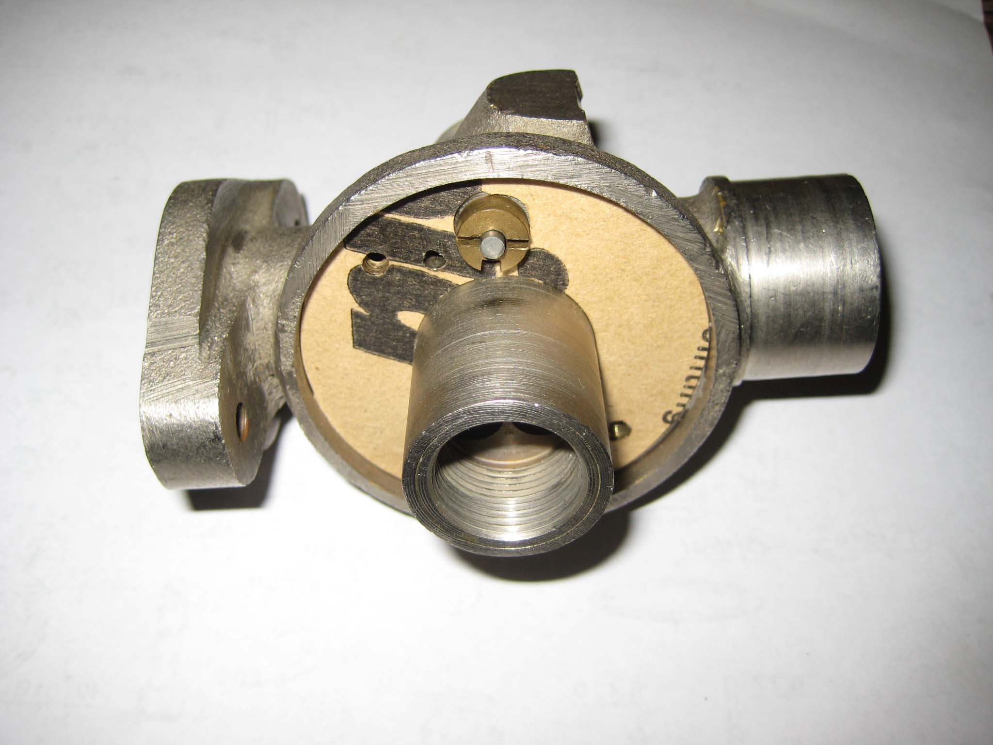
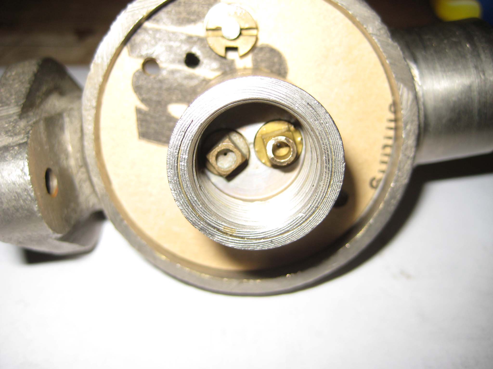
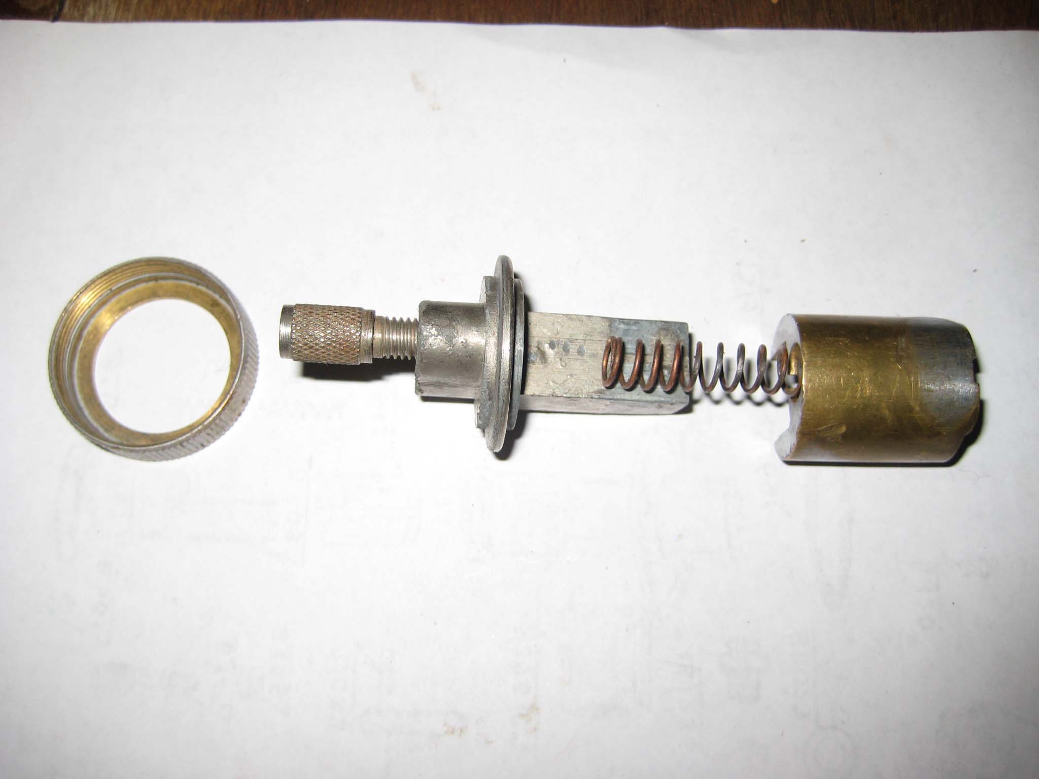
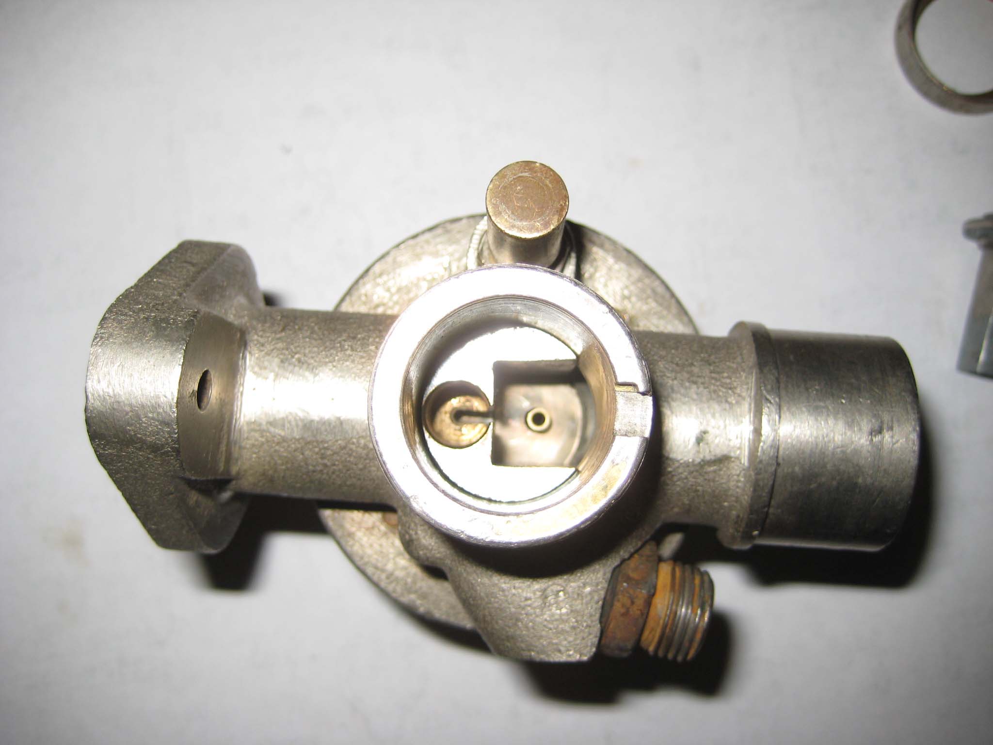
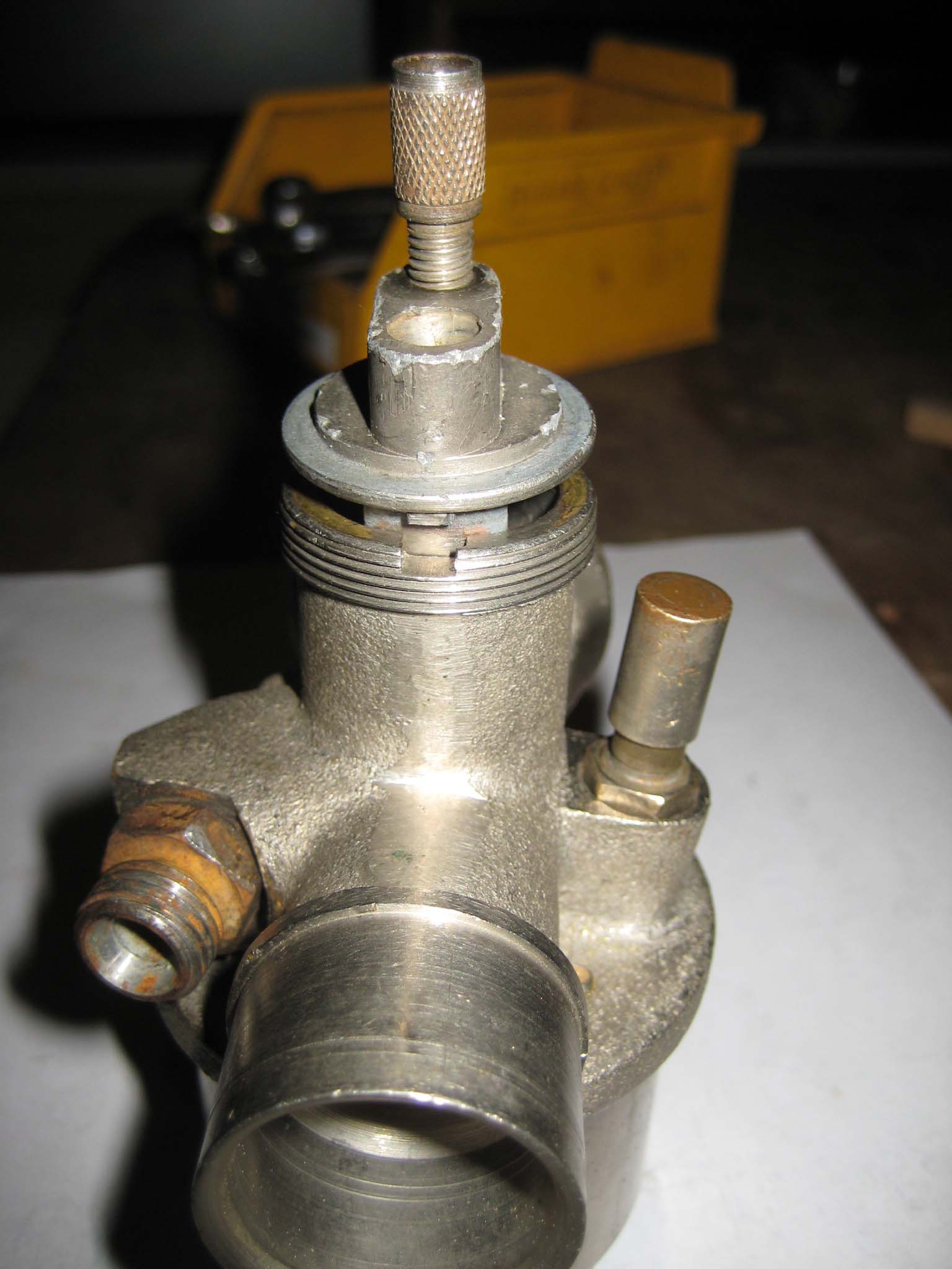
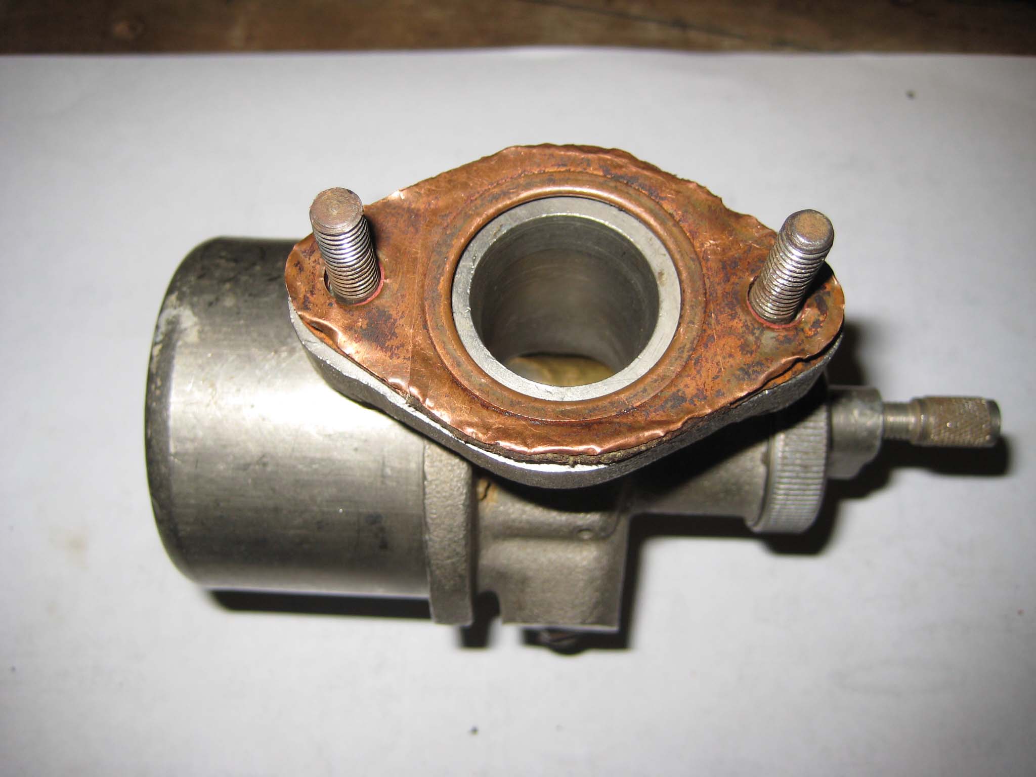
The size 70 main jet had a tubular extension at the inlet end, whereas the size 60 jet from the other carb does not (Carb 0001). I do not know what purpose this extension serves, but as this was the part of the jet that was damaged (Carb 0002), my only option was to cut it off (Carb 0003). A new paper gasket was fitted into the main body of the carb (Carb 0004). The idle and main jets (Carb 0005) were screwed into place using a 5mm square drive radiator key (Carb 0006). Two small slotted head screws hold the paper gasket in place (Carb 0007). Also visible in this picture is the needle holder and needle which allow fuel to enter the float bowl. The large brass plug which covers the jets was screwed into place (Carb 0008). According to the part list, this item is know as the filter adaptor and should have a filter gauze fitted inside it. Neither of my carbs contained this gauze, so currently none is fitted. The fuel supply line nipple was fitted, along with a fibre washer (Carb 0009). On the opposite side of the carb body, the tickler body was screwed into place (Carb 0010) and the tickler inserted through it (Carb 0011). The tickler is held in place by a 1.6mm diameter split pin inserted through the end that projects into the float bowl (Carb 0012). The float and float bowl (Carb 0013) were fixed into place by a bolt and copper washer (Carb 0014). The bolt screws into the filter adaptor, so it is important not to over tighten as damage to the jets could result. The last bits to be fitted were the throttle slide parts (Carb 0015, 16 & 17). I have deliberately left some parts off the throttle, as these will be fitted later with the throttle cable. The carb is fixed to the engine intake/exhaust manifold by two M6 studs and a copper gasket (Carb 0018 & 19). The gasket has seen better days, but it is still usable.Attachments:
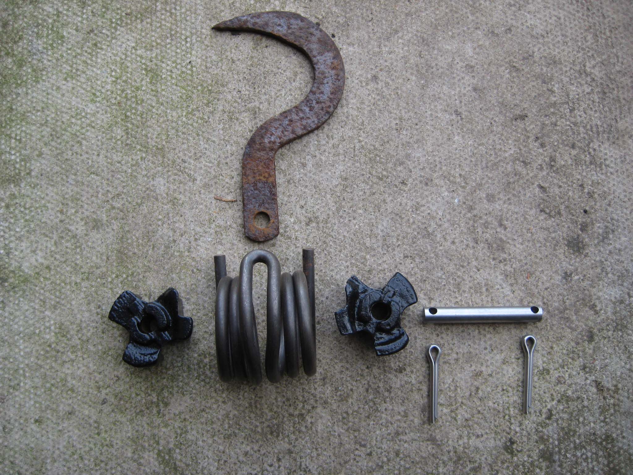
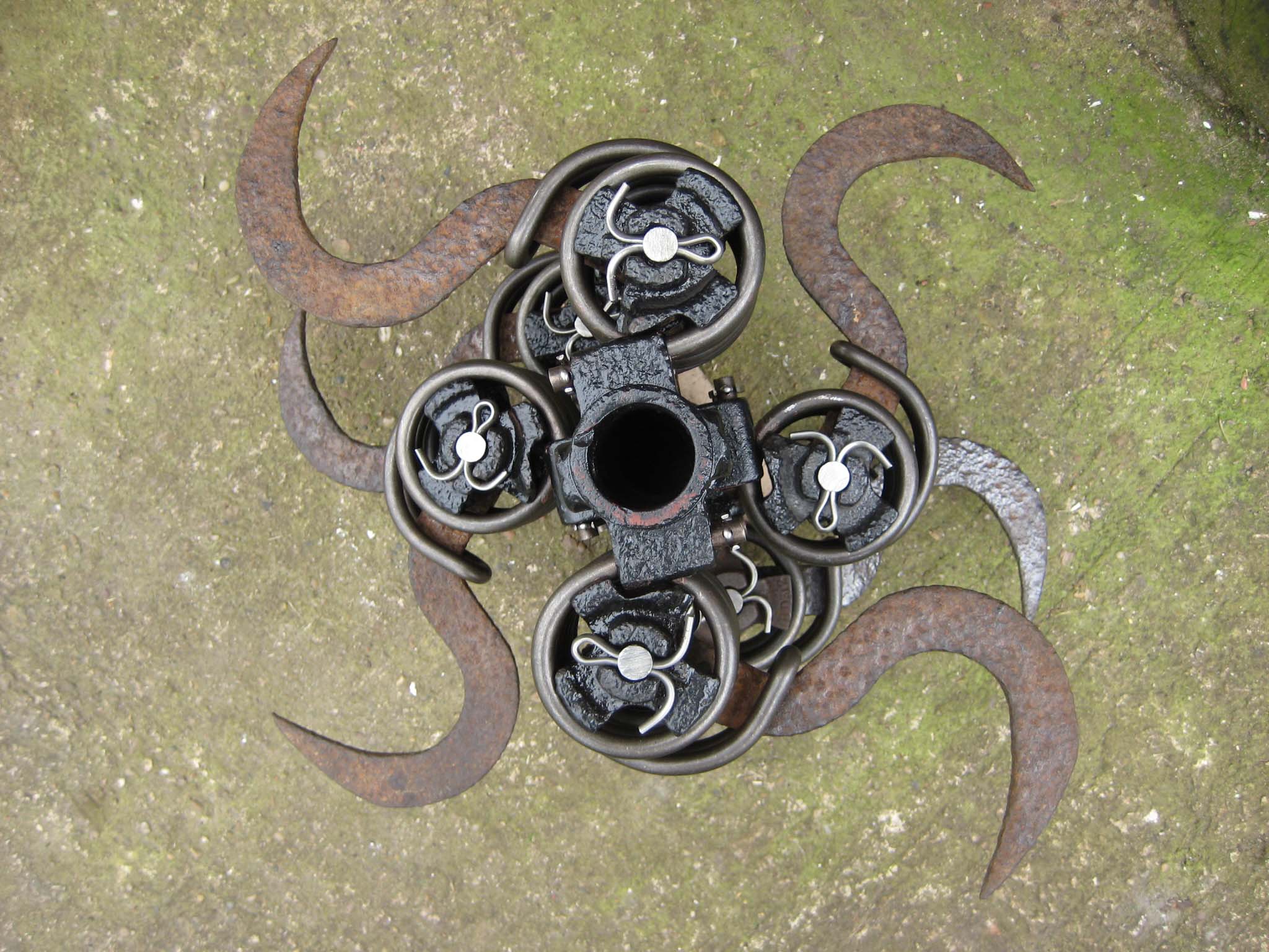
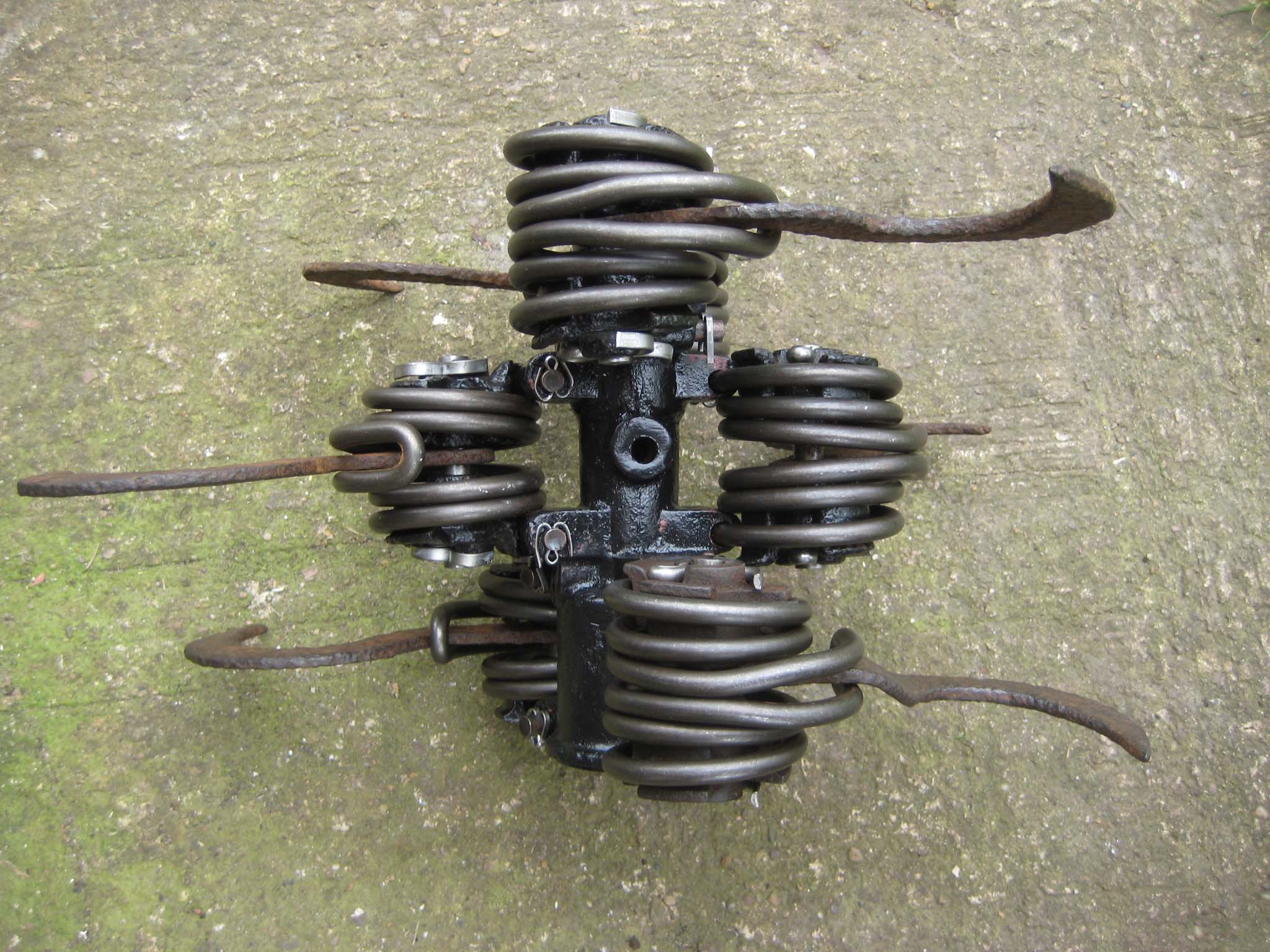
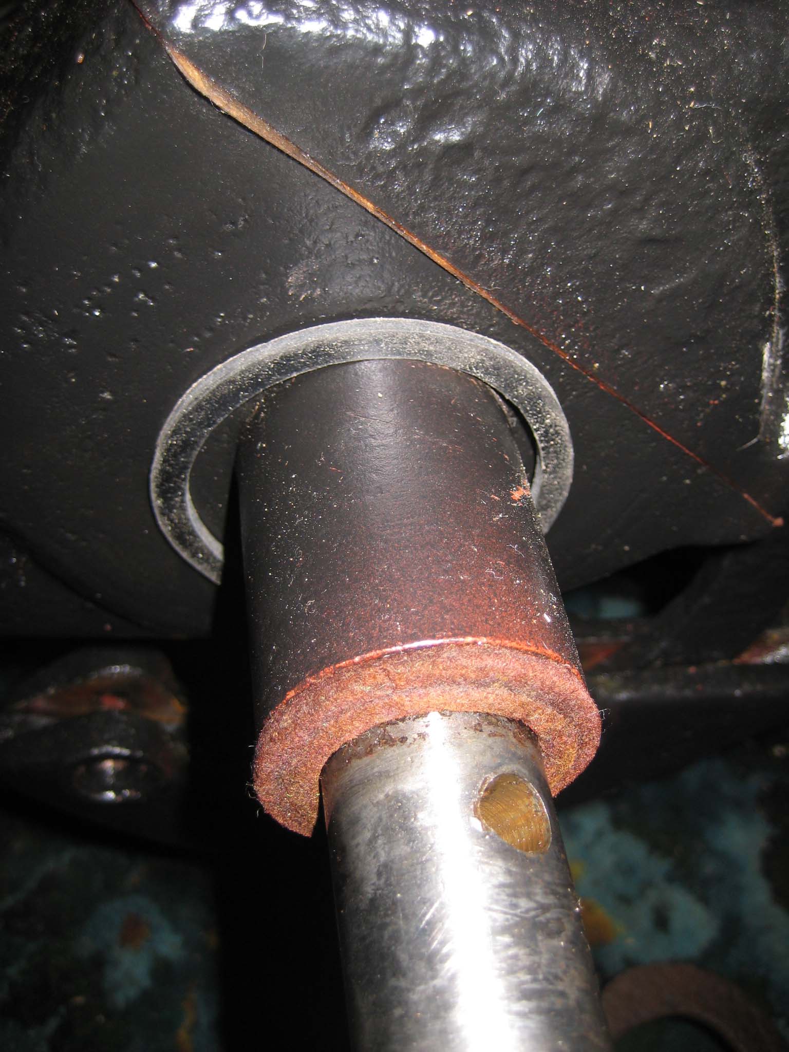
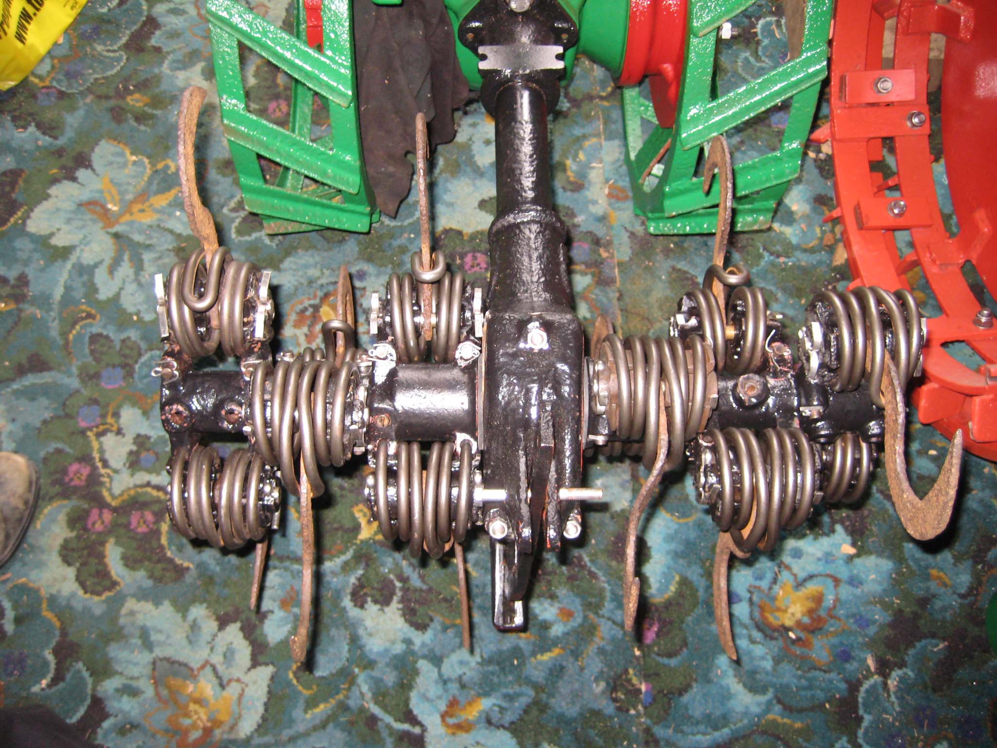
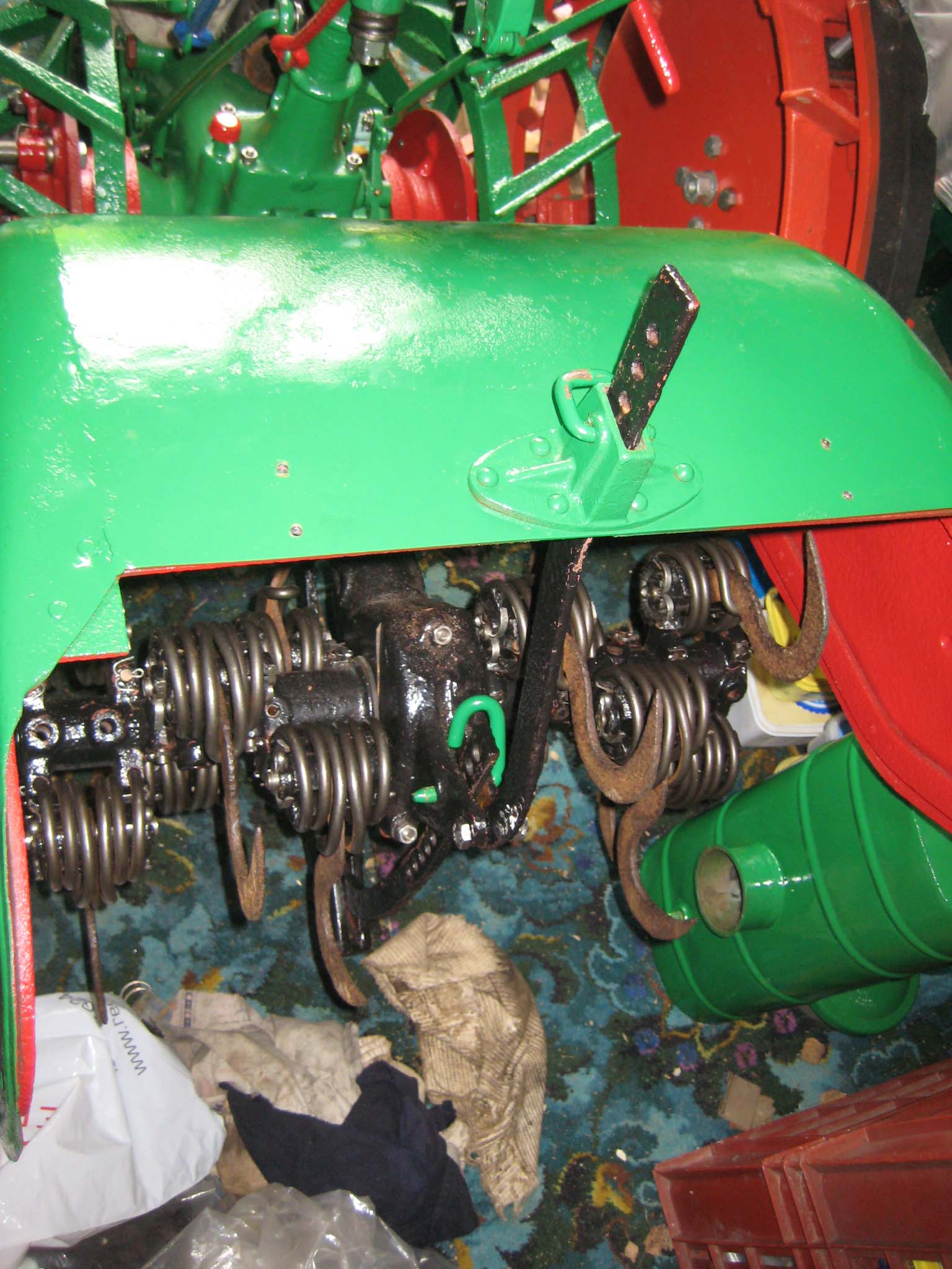
April 17, 2016 at 4:48 pm #20552vhgmcbuddyMemberAfter taking the plunge and having new tine springs manufactured, it was time to fit them. Each sprung tine consists of the spring itself, two handed castings, a pivot shaft and the tine (Simar 0102). The two castings fit into either side of the spring with the tine sandwiched between them. The pivot shaft then passes through the whole lot and is secured at both ends by two 6mm diameter split pins. Six of these sprung tine assemblies are fitted to the miller sleeve castings (Simar 0103 & 4). Before fitting the miller sleeves, felt washers were slid over the driveshaft. Also, I made Nitrile rubber seals to fit between the miller sleeves and miller gearbox casing (Simar 0105). Originally, these would have been leather, but had long since rotted away. The miller sleeves are held in place by four 10 x 60mm roll pins, 2 per side (Simar 0106).
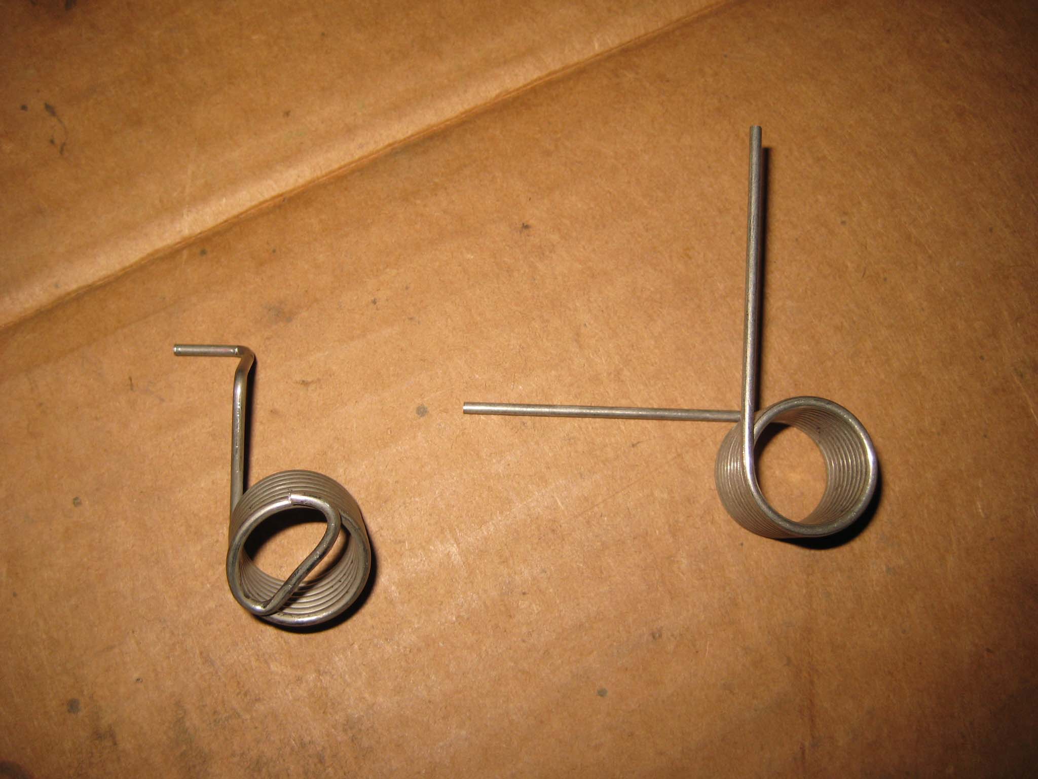
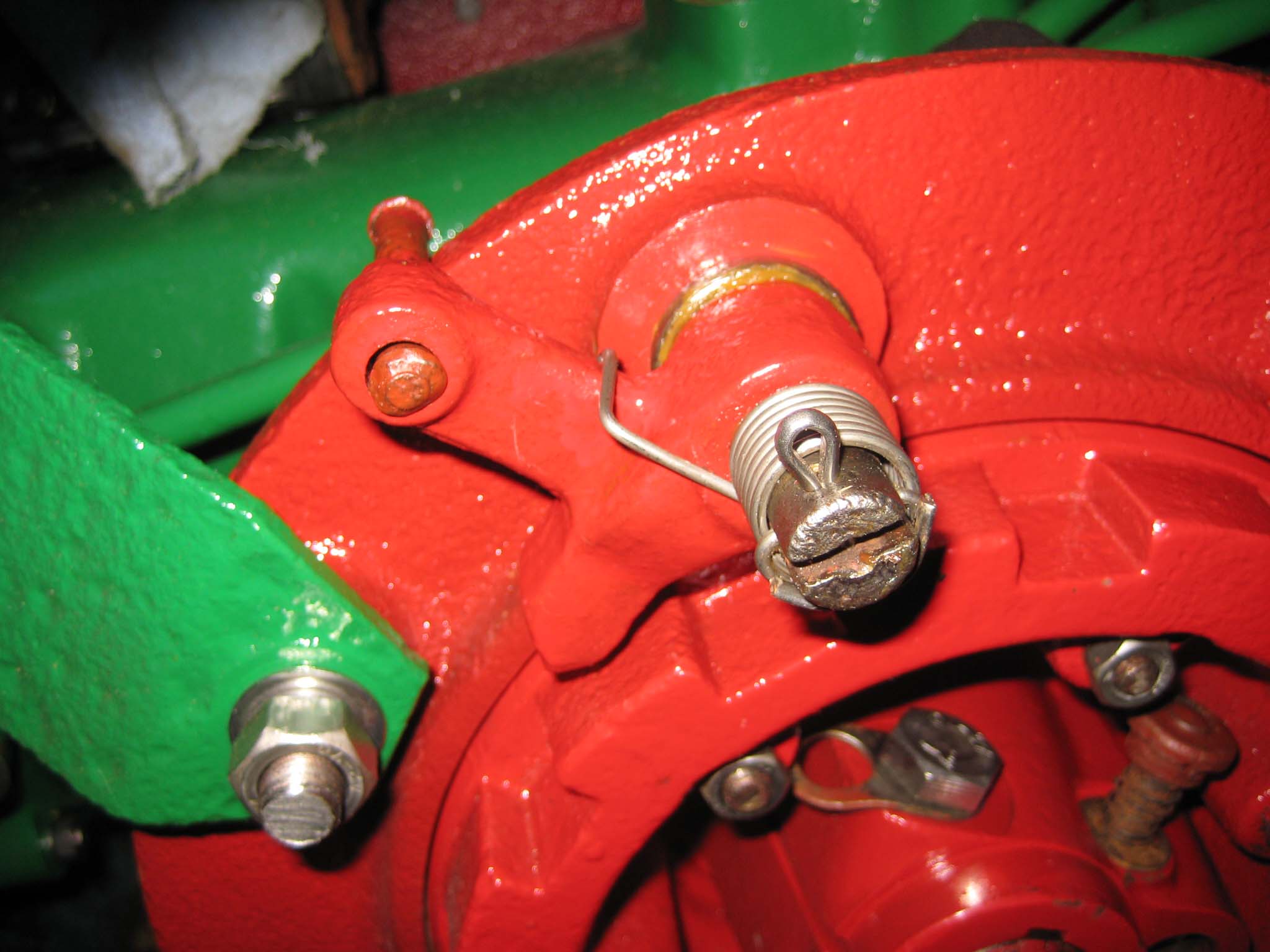
I had also managed to source suitable torsion springs for the wheel ratchet Red pawls, as the originals were missing. The new springs required some modifications before they could be fitted (Simar 0107), but this was reasonably straight forward using a vice and pliers. The Red pawls and springs were fitted to the wheel hubs and secured in place with a 4 x 25mm split pin (Simar 0108).
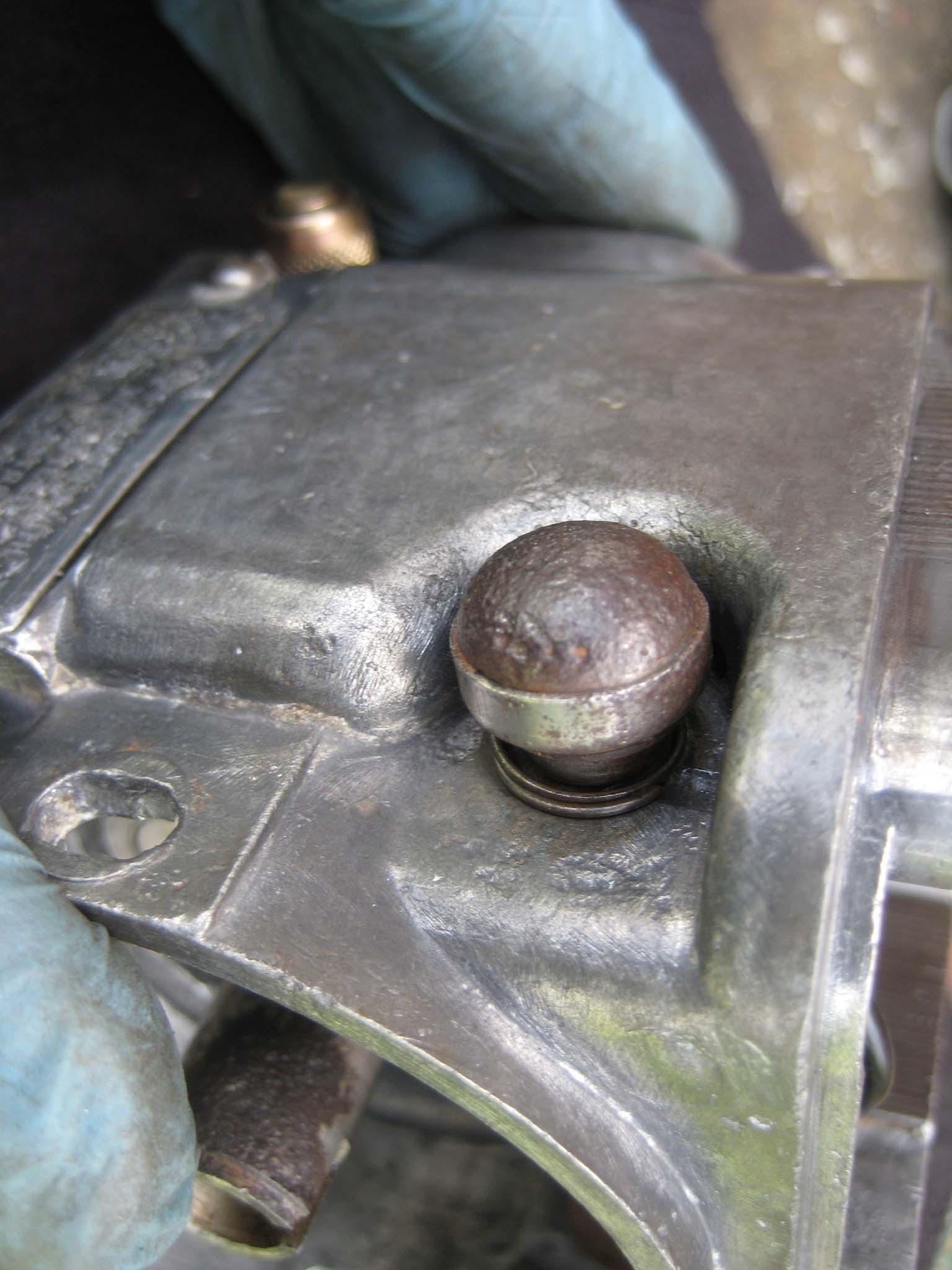
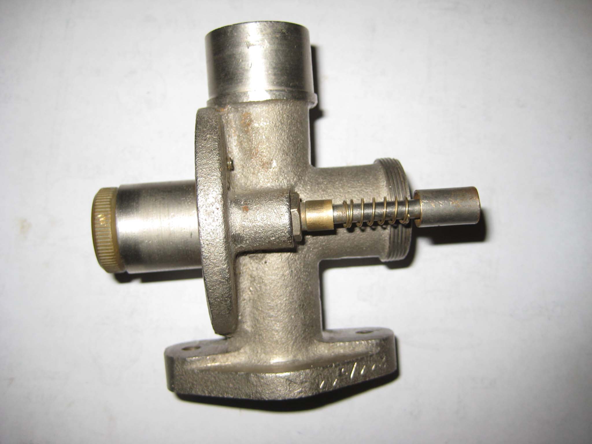
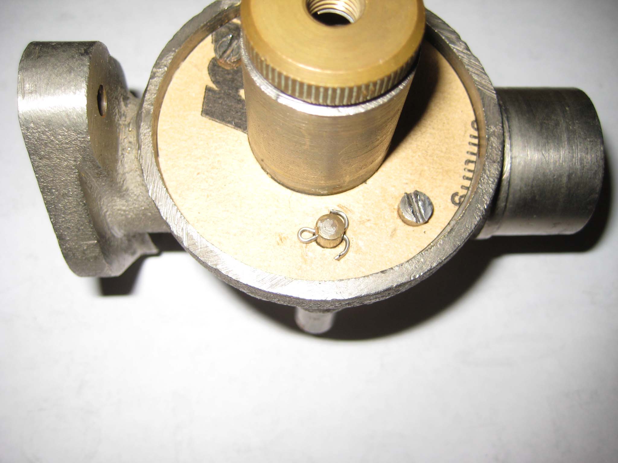
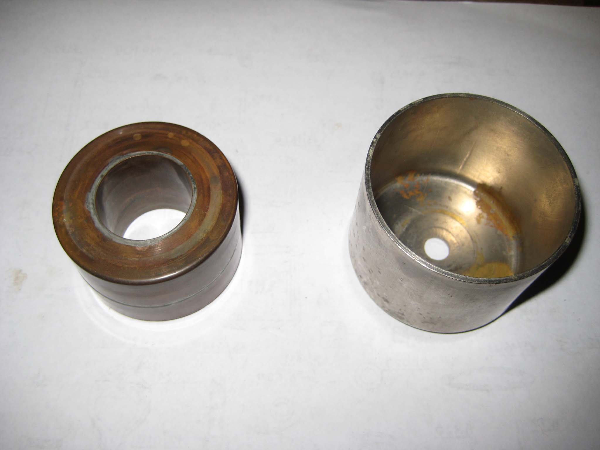
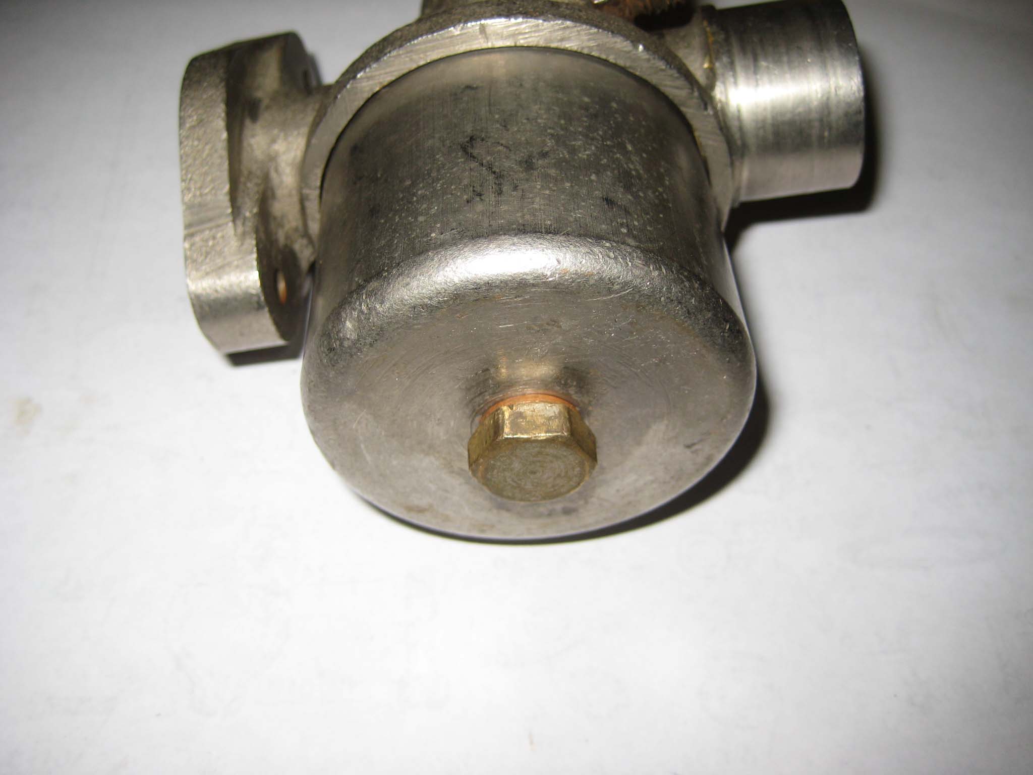
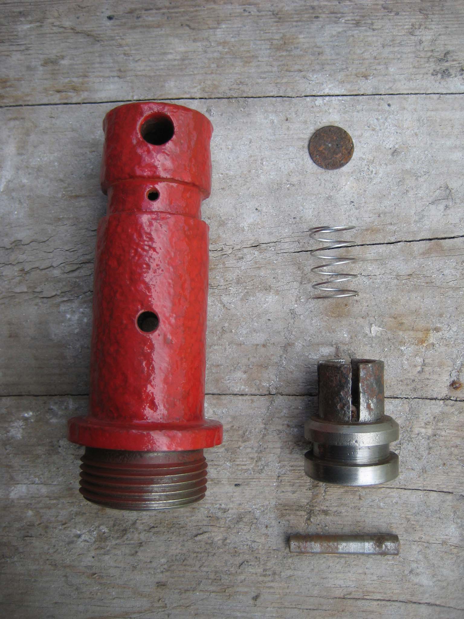
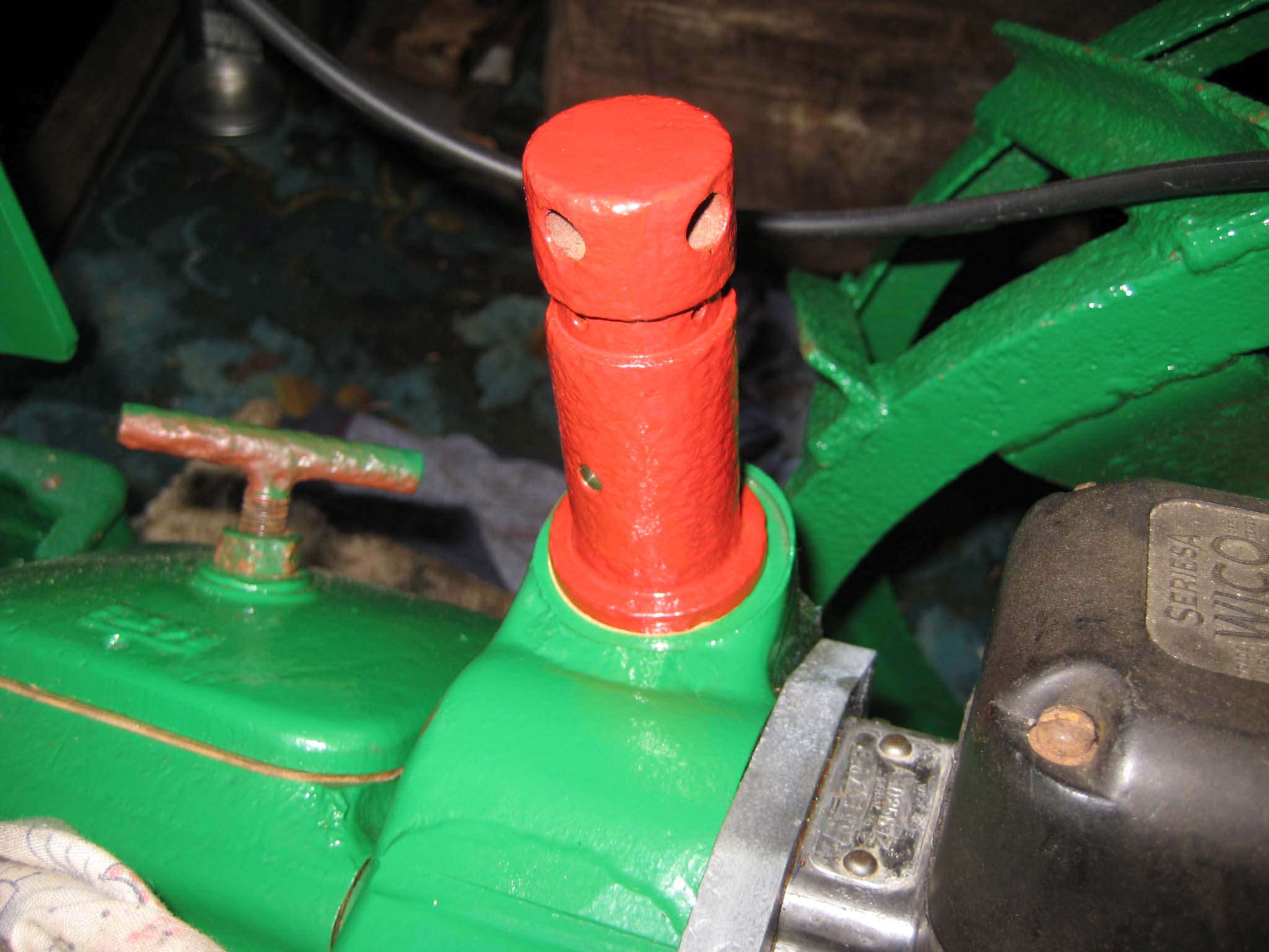
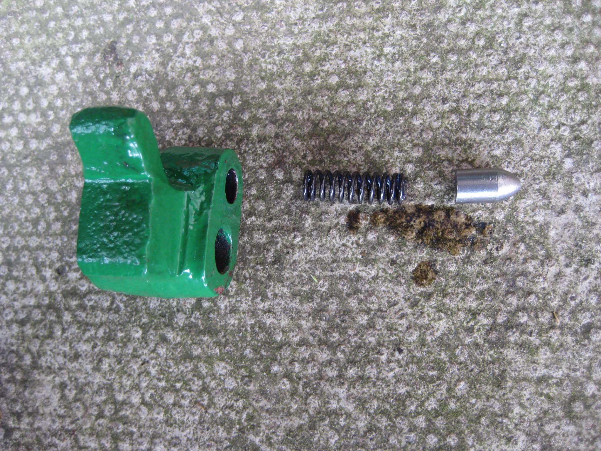
Another job requiring a new spring was the main gearbox breather (Simar 0109). The spring I used has a couple more additional coils than the original, but it’s uncompressed length, diameter and wire size were a match. It was the closest match available off the shelf without going to the expense of having a special made. Please note that when assembling the breather, the order of the parts shown in the manual is incorrect (my photo also shows the incorrect order). The breather disc should be fitted into the disc guide, with the spring fitted next, so the spring can hold the disc in it’s seat. This stops dirt from entering the gearbox, but excess pressure inside the gearbox can unseat the disc. The breather disc guide is held at the top of the breather body by a 5 x 30mm taper pin. The breather was then screwed into the main gearbox, complete with a new paper gasket (Simar 0110). The hole the breather is screwed into is also the oil fill point for the main gearbox.Attachments:
April 18, 2016 at 3:32 pm #20577 charlieKeymaster
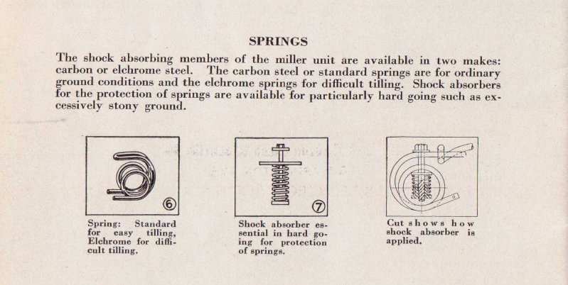
I dread to think what those springs for the tines cost! A recent booklet I bought from Donald Jones in the USA via that online auction site shows a shock absorber for the other type of tines, see photo.
Attachments:
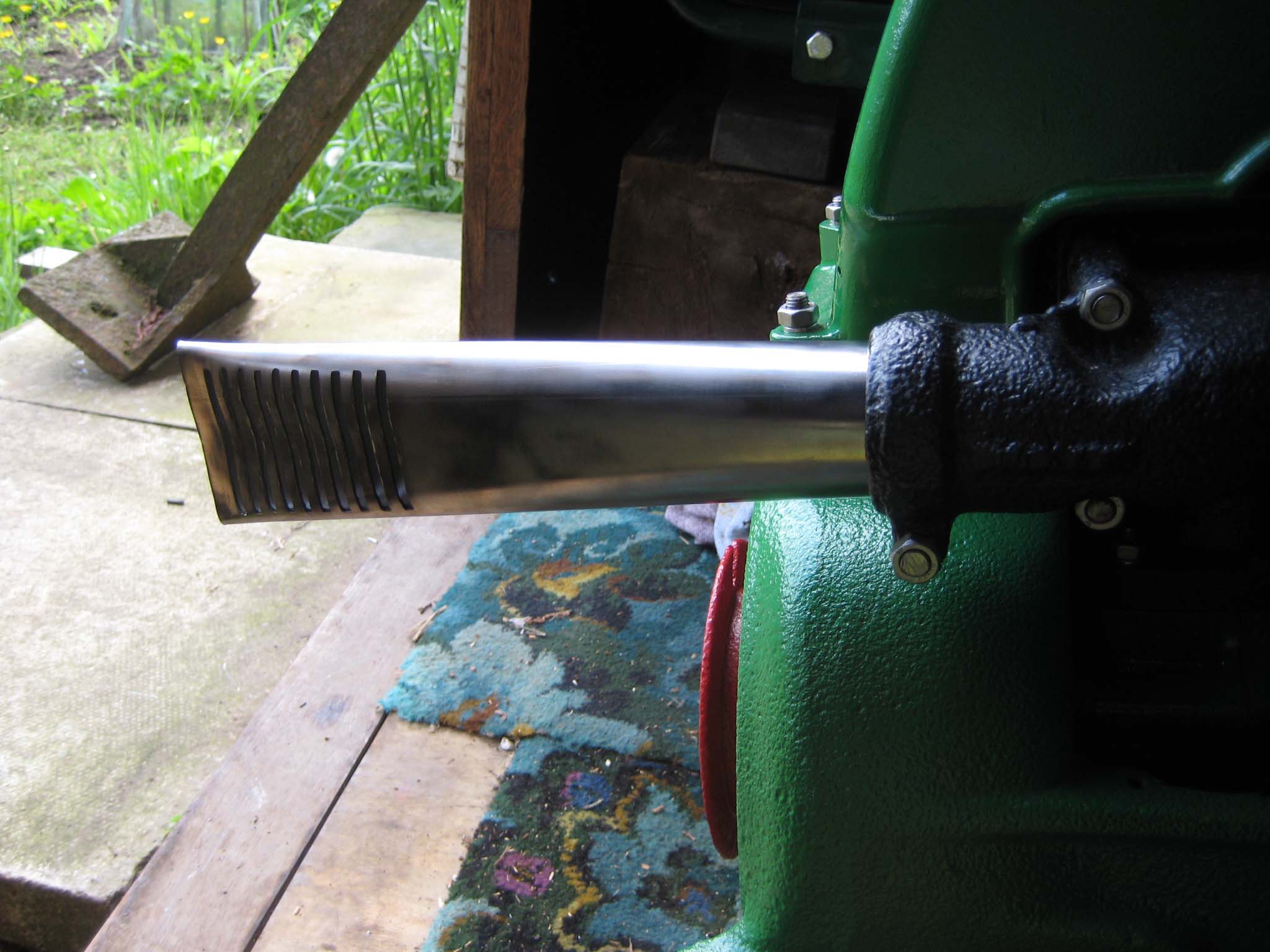
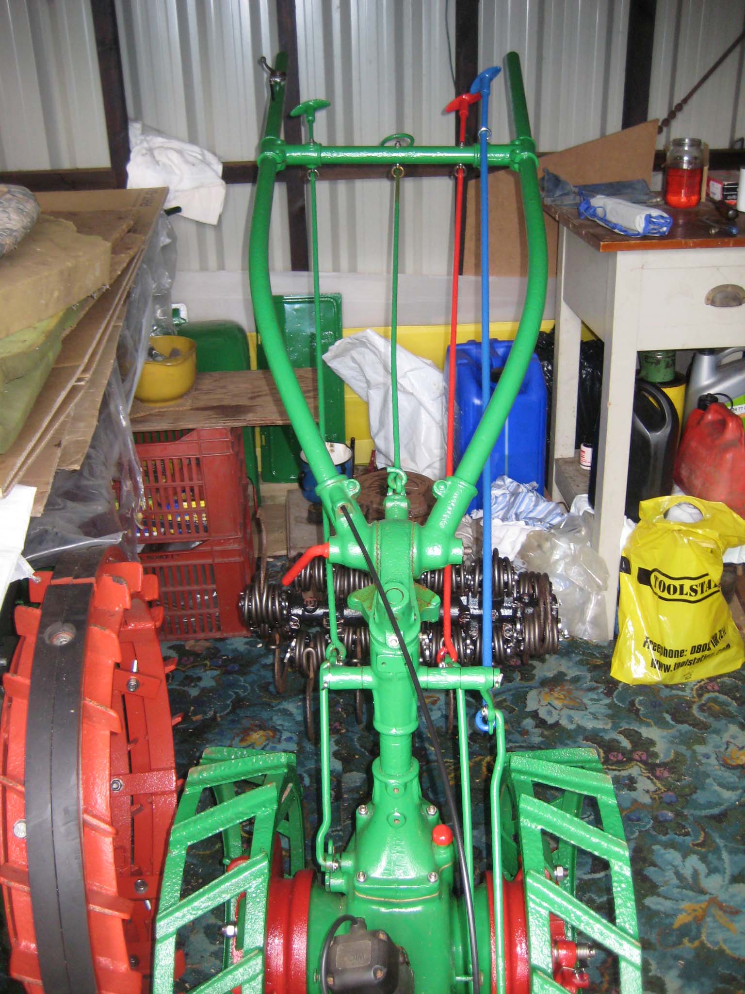
September 15, 2016 at 6:46 pm #22366vhgmcbuddyMemberMade a new fishtail exhaust tailpipe by squeezing a piece of tube between two wedge shaped bits of timber. Didn’t quite get the wedge angle correct, so the pipe is longer than it should be (Simar 0111).
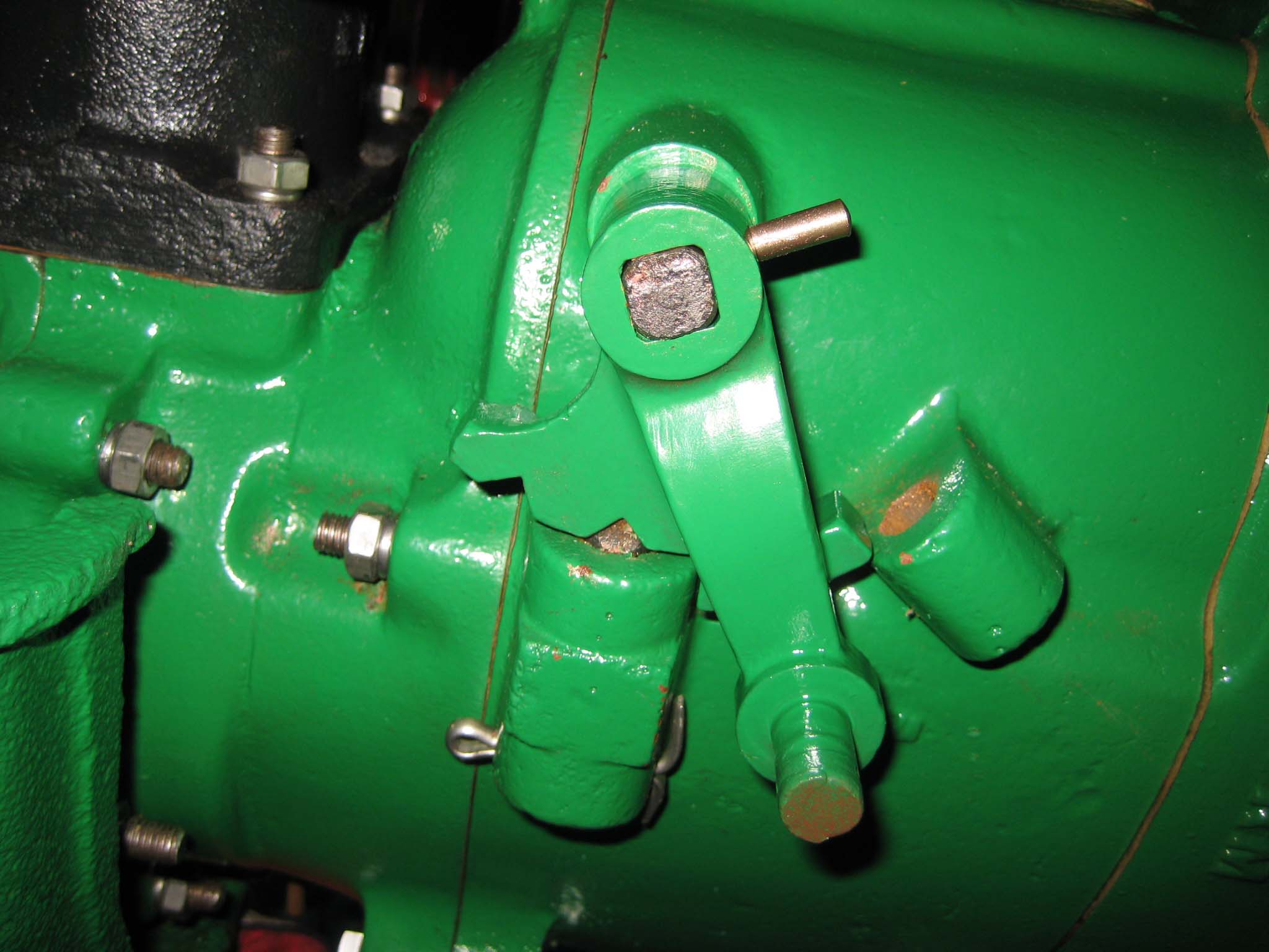
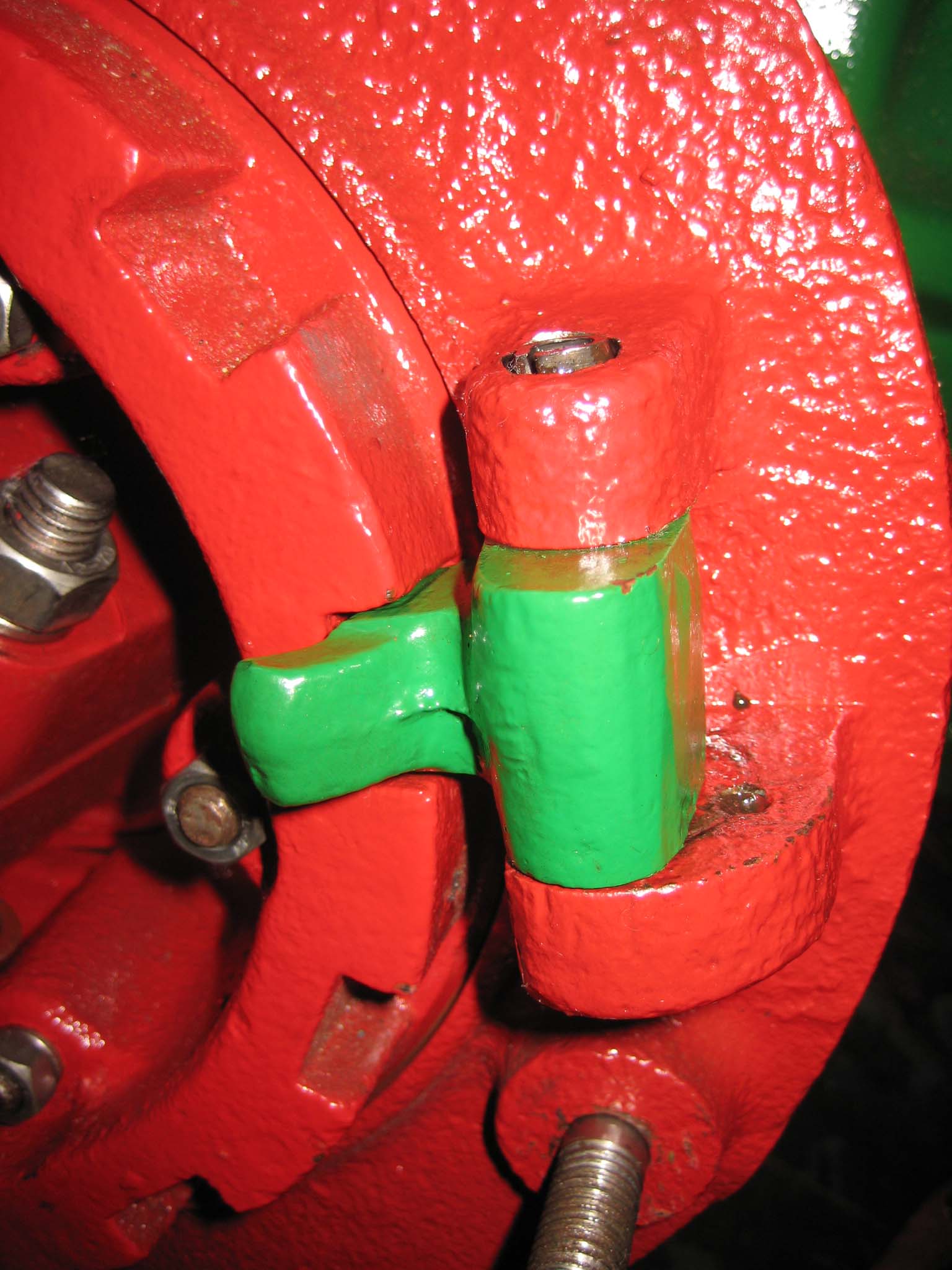
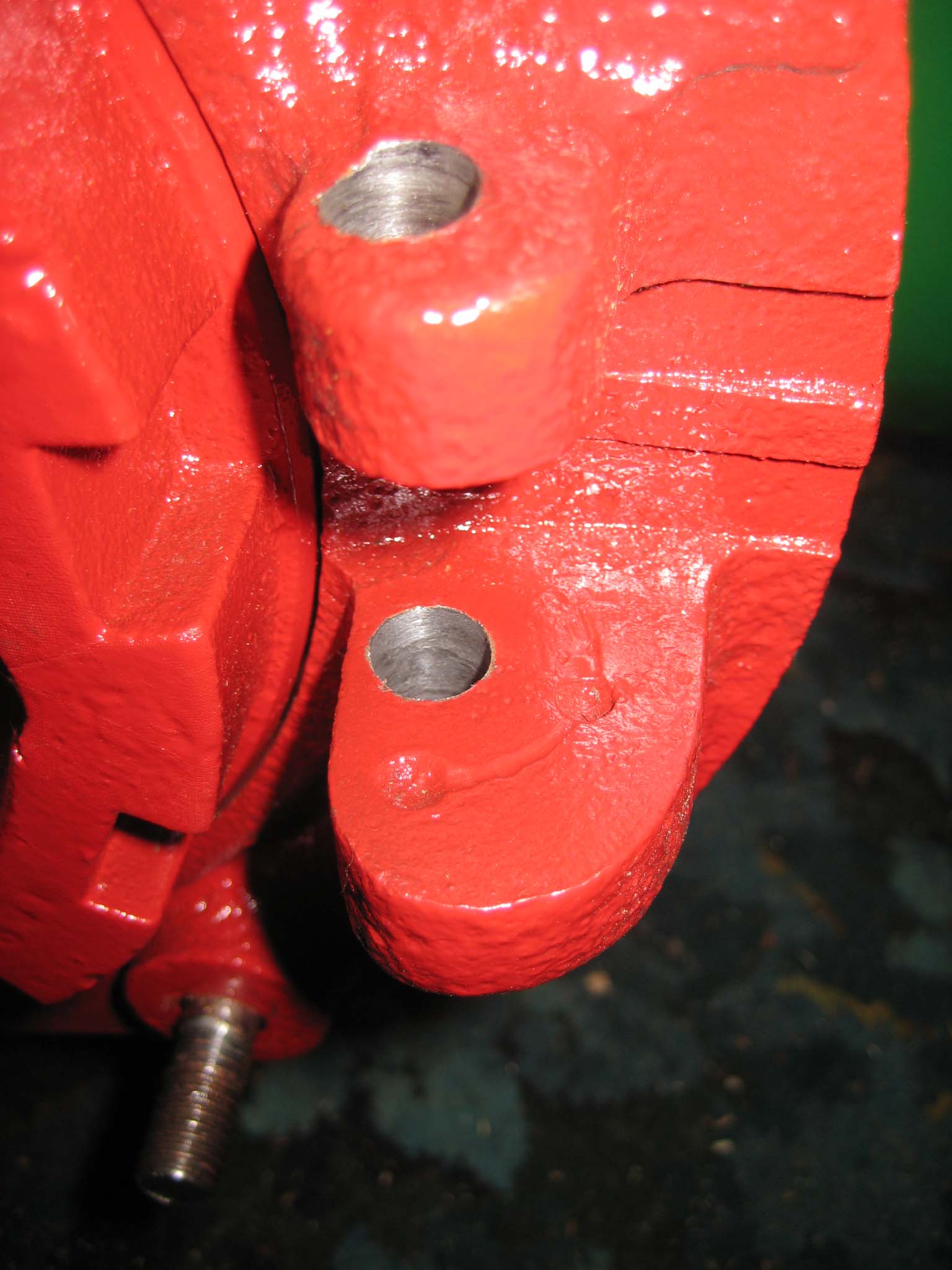
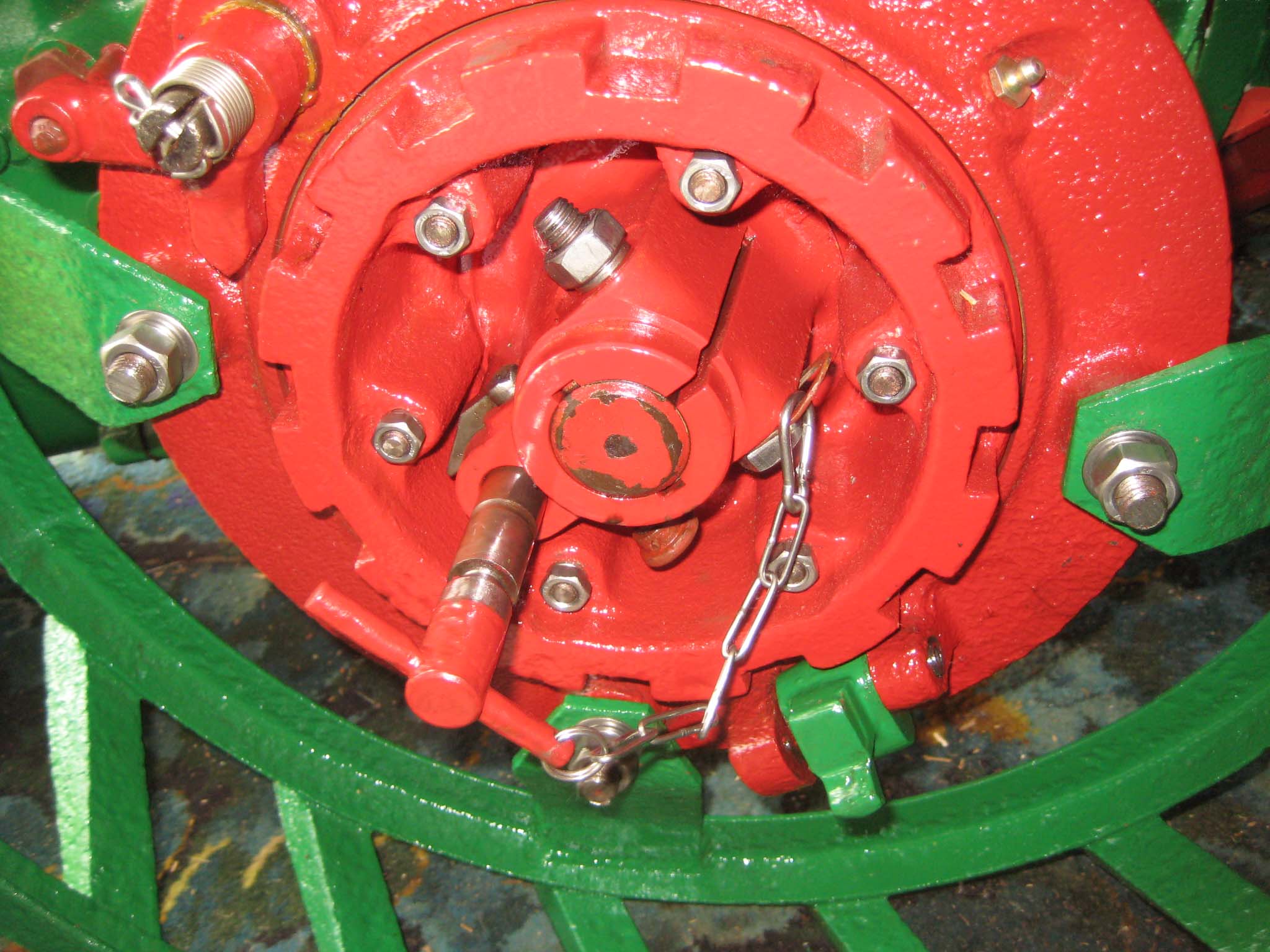
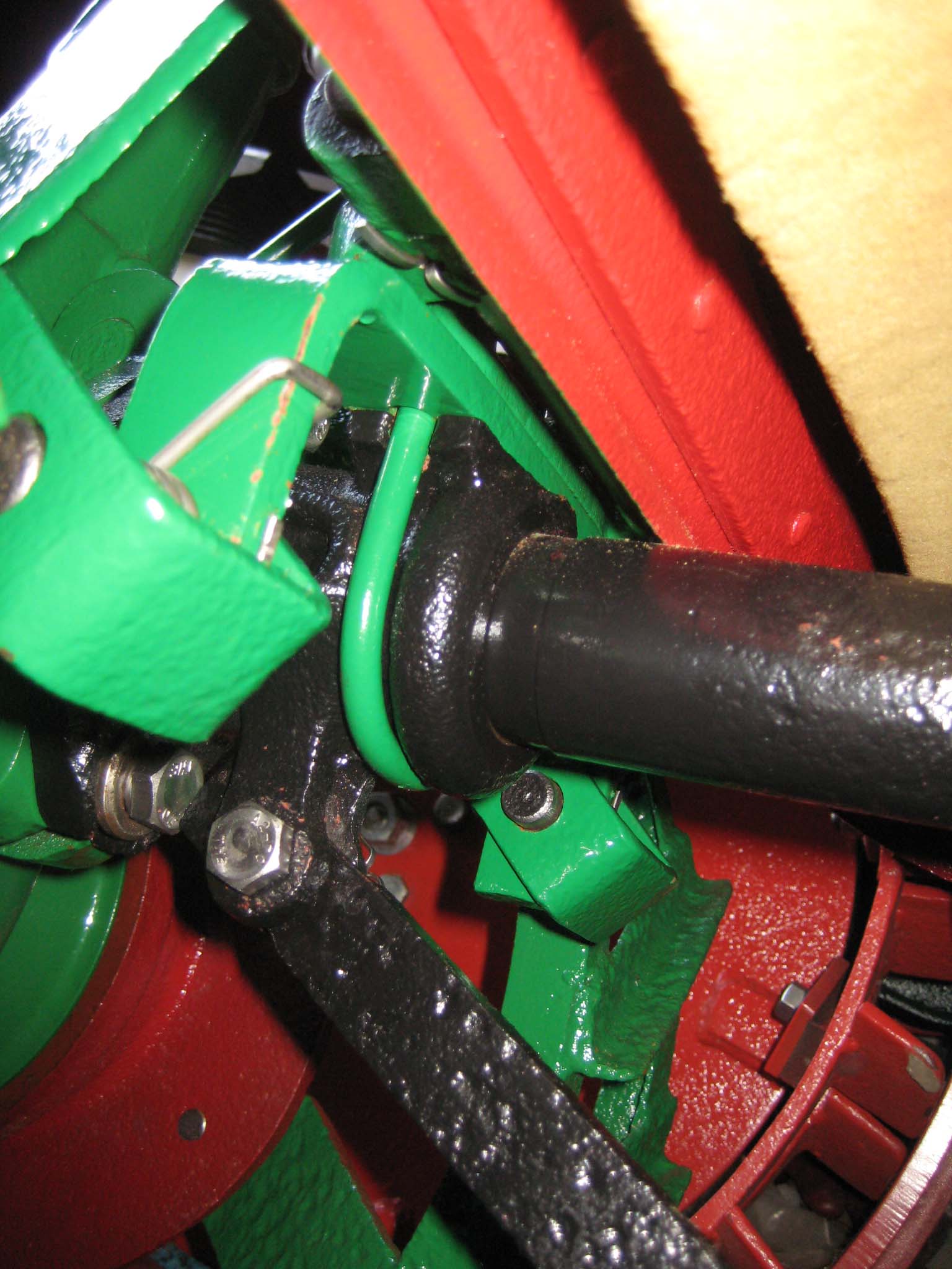
The Green locks for both wheel ratchets (Simar 0112) were fitted to the hubs using 10 x 65mm roll pins. The mounting lugs on the wheel hubs have slightly larger holes than the Green lock, so the roll pin grips the lock, but is free to turn in the wheel hub lugs (Simar 0113). The sprung plunger inside the Green locks locates into small indentations in the larger mounting lugs, holding it in either the locked or unlocked position (Simar 0114). To complete the wheel hubs, I added chains to the two gear selection pegs (Simar 0115). Each chain has a Karabiner clip at one end so it can be removed along with the peg when selecting the desired forward speed. The longer peg selects either low or high speed depending into which hub it is inserted. The shorter peg is a blank for the whichever hub doesn’t have the long peg in it.
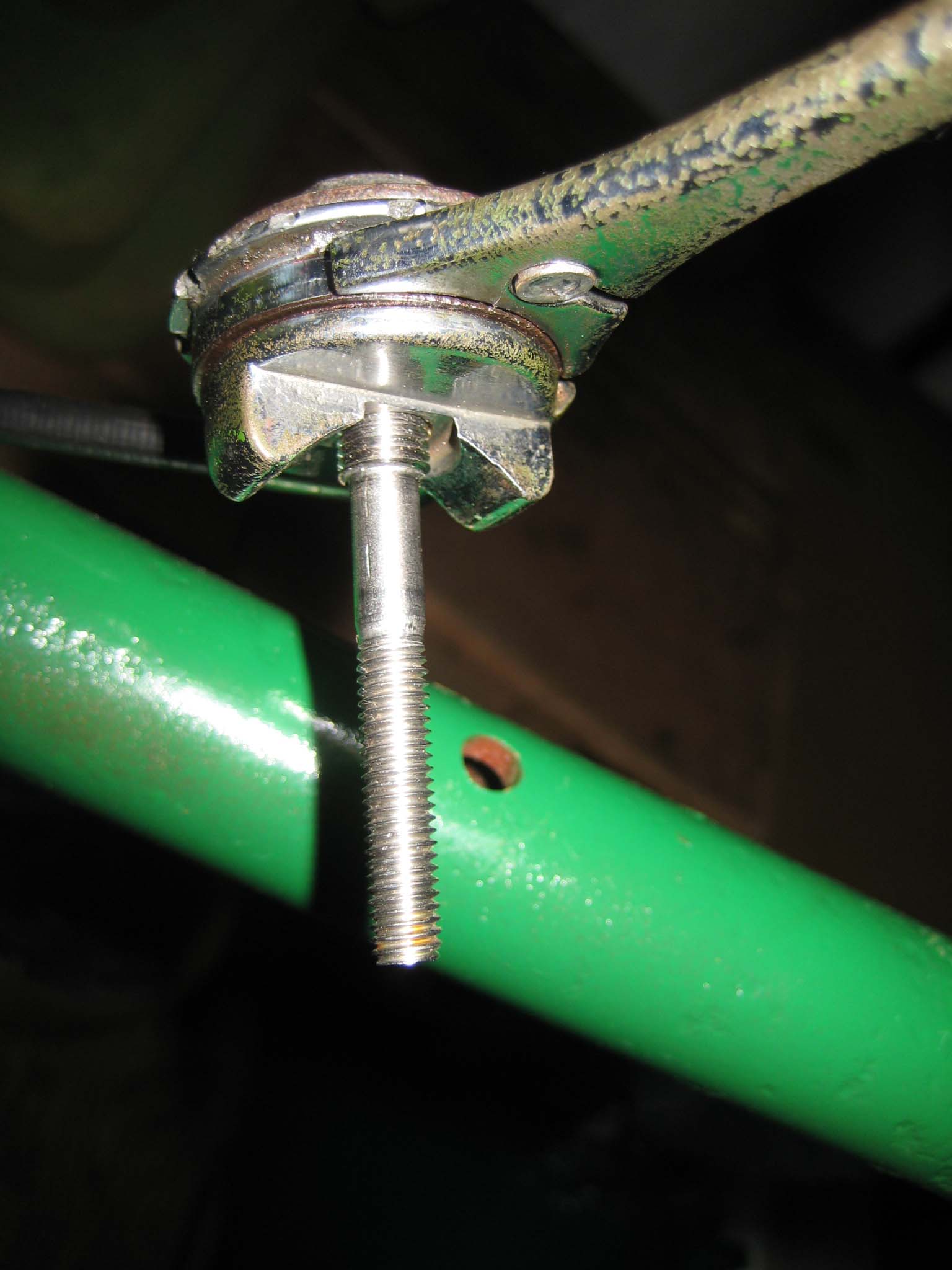
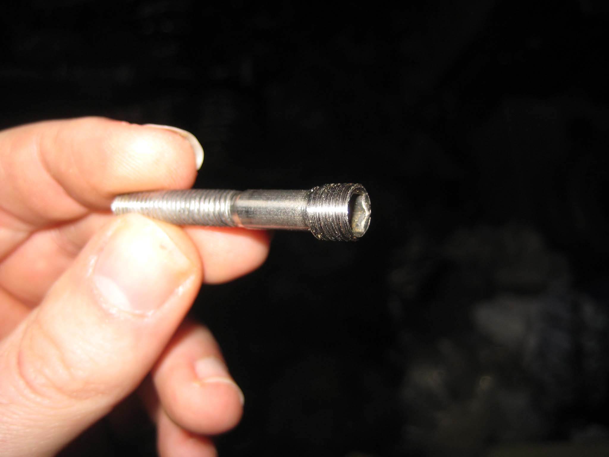
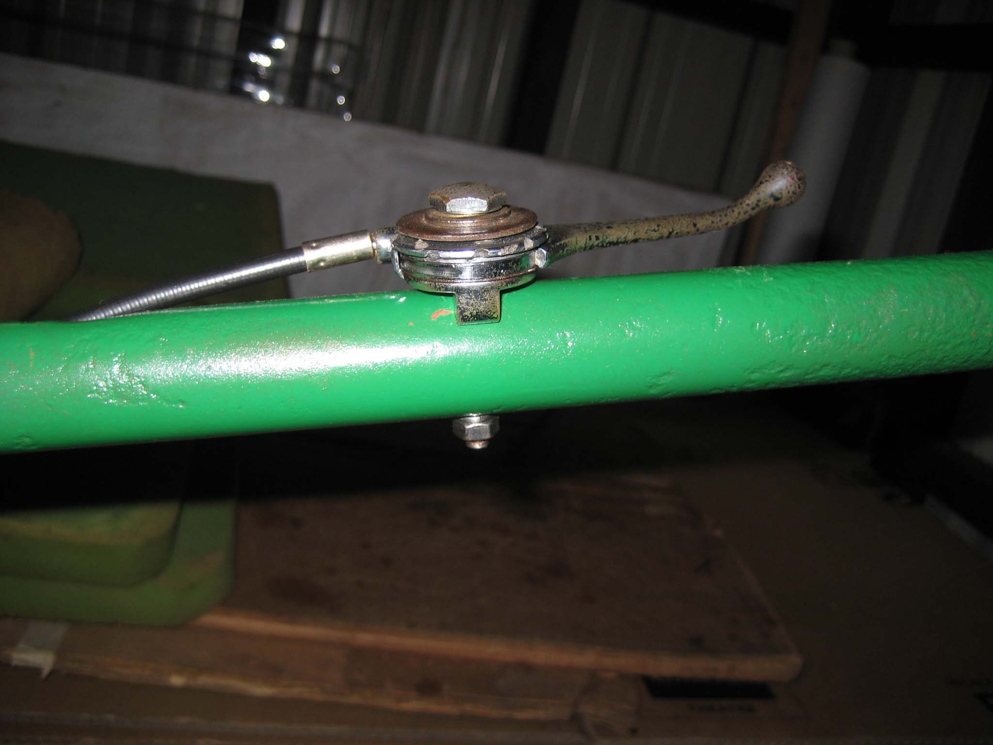
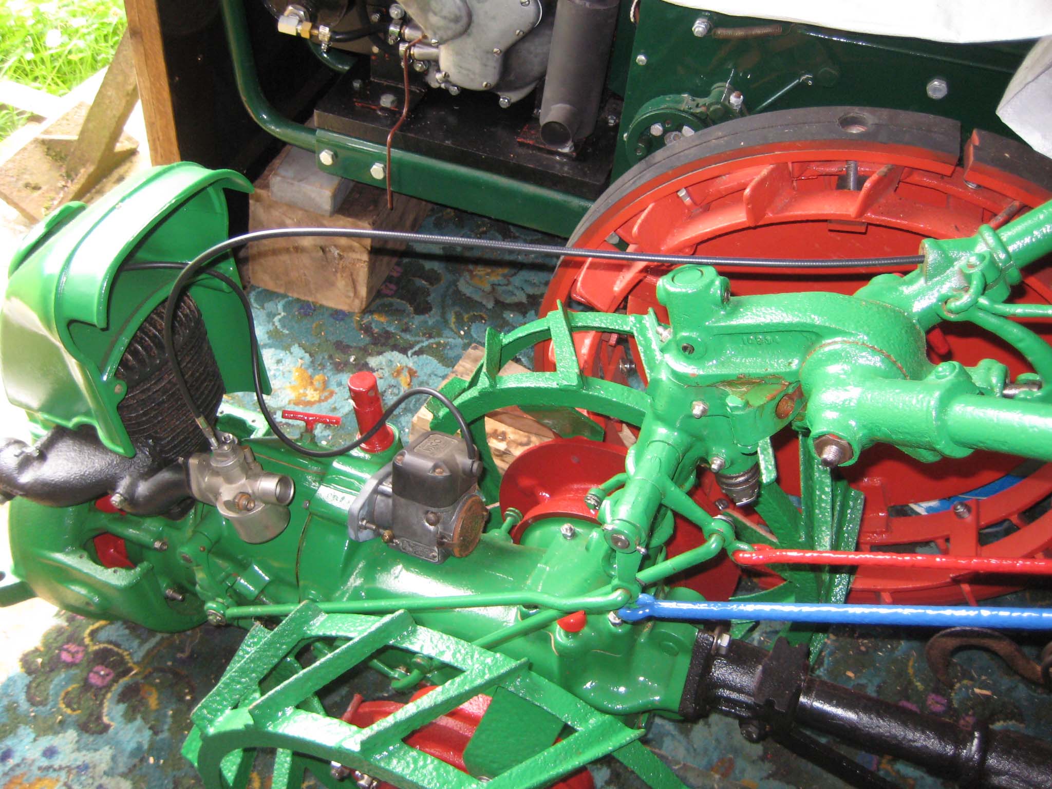
The throttle control is held in place by a special stud (Simar 0116). As the original stud was badly corroded, I made a new one from a M6 x 40 allen head cap screw. The cap screw head was turned down to 5/16″ diameter and then threaded to 5/16″ BSCY (Simar 0117). The 5/16″ BSCY end screws into the base of the throttle control with the M6 portion of the stud passing through the handlebar tube (Simar 0118). A new throttle cable was made and threaded down the inside of the right hand handlebar and joined to the carburettor (Simar 0119). The control rods for forward (Red), reverse (Blue) and the miller (Green) were reattached to the steering column (Simar 0119 & 20) via a long cross shaft.Attachments:
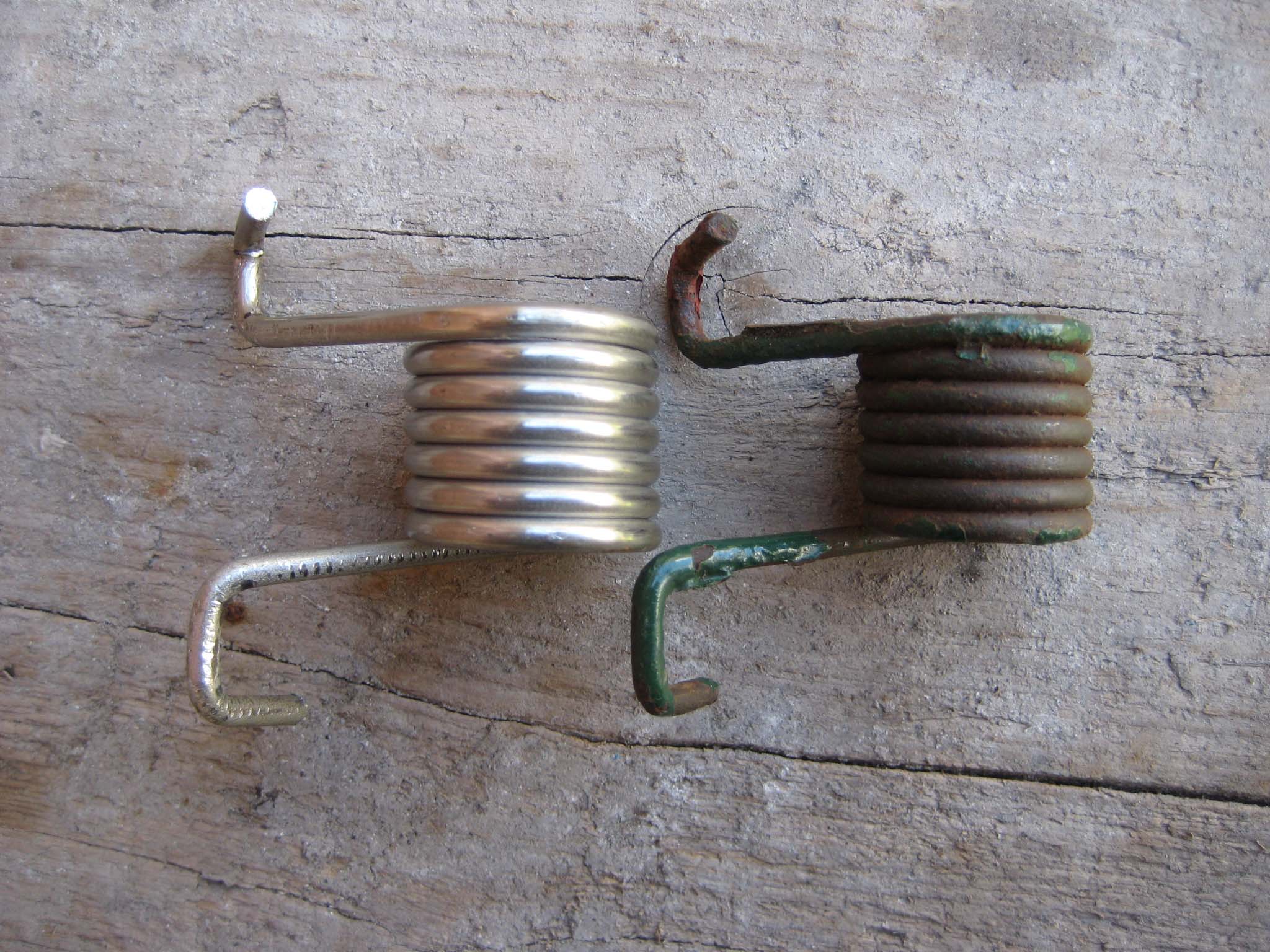
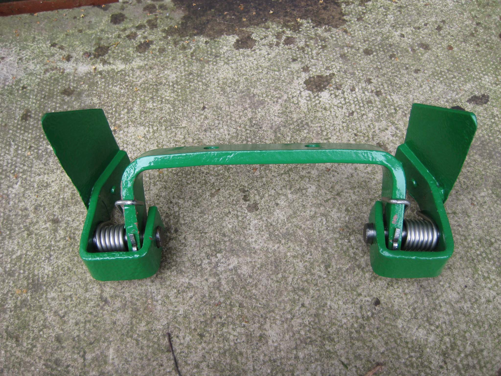
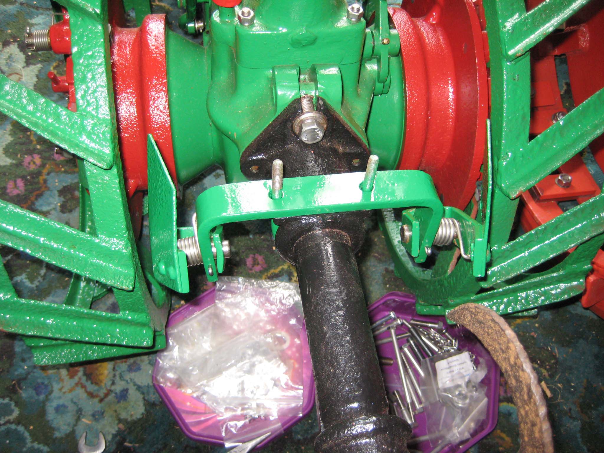
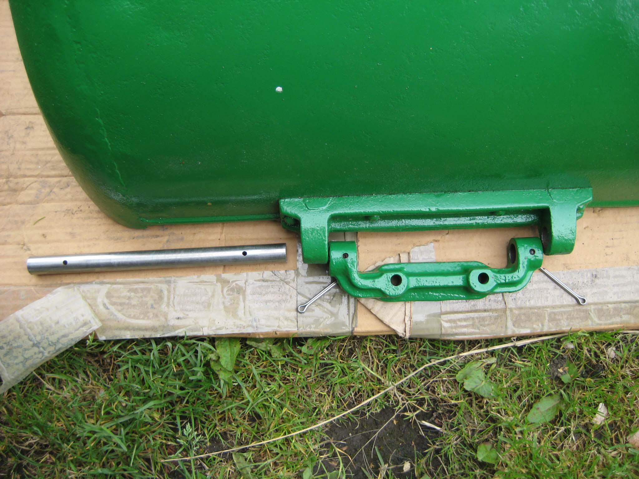
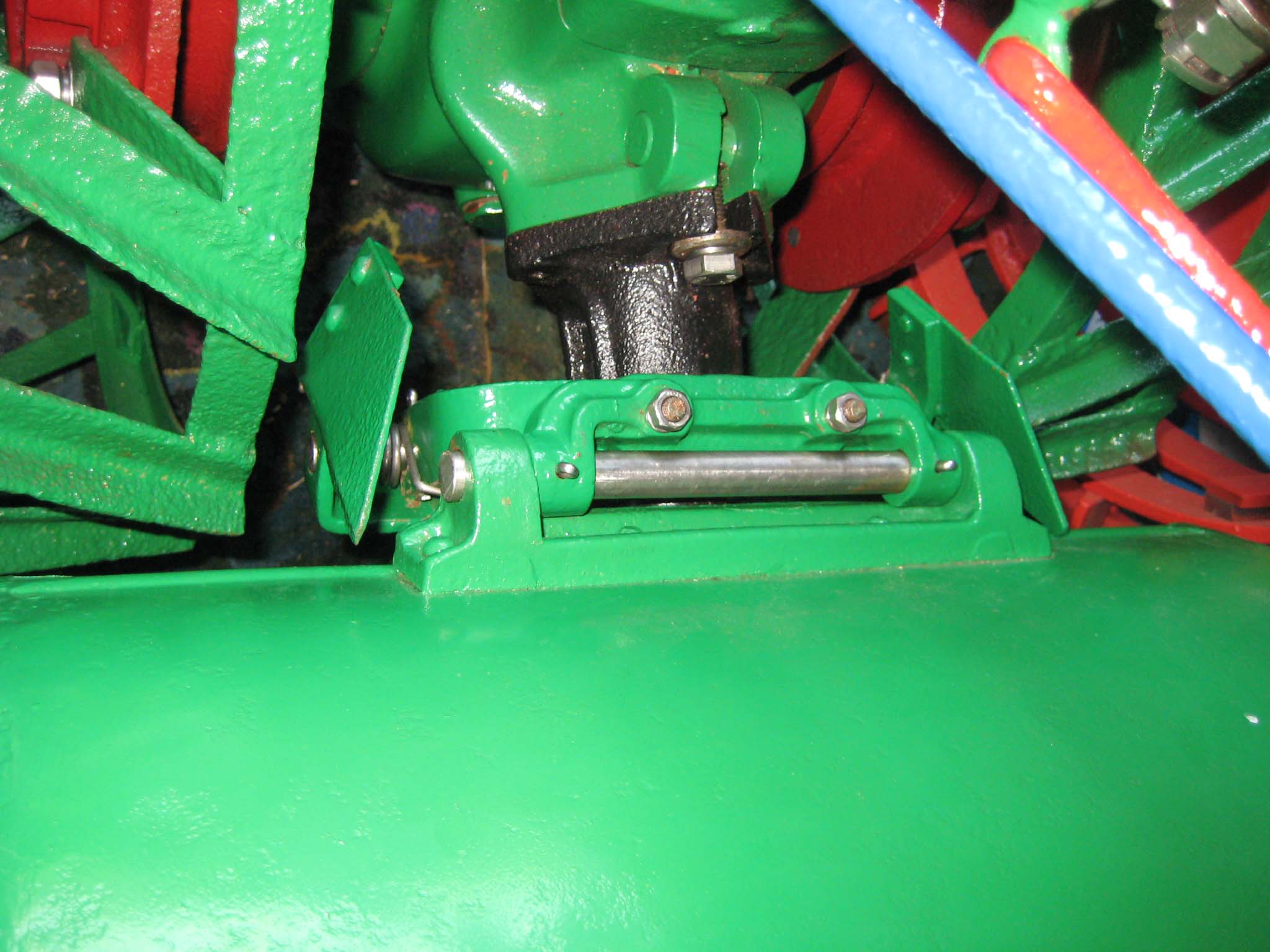
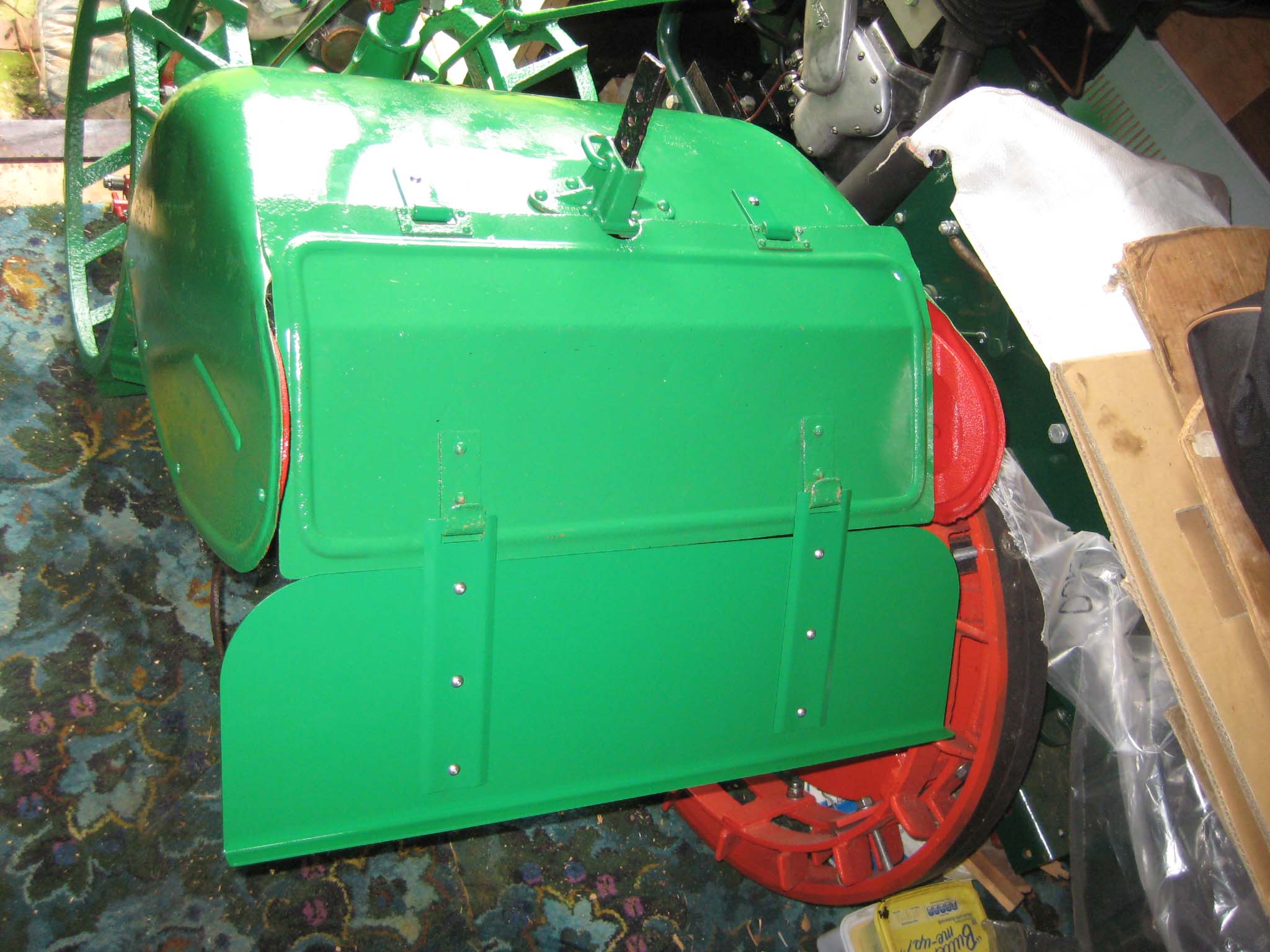
September 16, 2016 at 7:00 pm #22404vhgmcbuddyMemberMy machine was missing the mud scraper assembly which is sandwiched between the miller PTO drive shaft housing and miller cover. Fortunately the Charlie Moore Emporium of SIMAR Spares came to the rescue with a suitable replacement (Simar 0121). I made replacement springs (Simar 0122) for the scraper assembly. Even though the originals were perfectly usable, I decided to keep these for use as patterns should I ever need replacements. The scraper is held in place by a U-bolt (Simar 0123 & 4). I could not source an ‘off the shelf’ U-bolt of the correct size, so had a Blacksmith make it. The miller cover has a hinged casting at the front (Simar 0125), which sits on top of the scraper (Simar 0126). At the rear of the miller cover is the height adjustment bar (Simar 0127). Immediately below this is the depth regulating bar. Both retaining pins were Blacksmith made to dimensions supplied by Charlie taken from the drawing archive held at the Museum of English Rural Life, Reading. The rear dust boards were then hung from the miller cover (Simar 0128). The miller cover and both dust boards were also missing from my machine. The miller cover and upper dust board came from our very own club shop keeper, Steve Woollas. The lower dust cover was manufactured to dimensions once again supplied by Charlie from the MERL archives. I did have to compromise on the half round swage which was pressed into the outer edge of the original, similar to that which can be seen on the upper dust board. To have this panel pressed would have cost in the region of £350. The panel minus the swages cost £10!!!
Attachments:
September 17, 2016 at 6:34 pm #22420 roatavatorParticipant
I’ve justcaught up with this thread.
Sean, the quality of your restoration and the clarity of your description and photos are amazing. They will surely prove invaluable to any other member brave enough to attempt the full works!
Charlie, I didn’t know you could get shock absorbers, could have done with them at Little Ellingham, very hard stony ground broke a spring on the 56 (and a couple on the A5). Sean, the breakage was one of the old ones, your new ones did fine, so they’ve cetainly passed the test now and you should have no problem with them. (But how you can stand the thought of working your 56 after all your painstaking work baffles me!)September 18, 2016 at 5:06 pm #22428vhgmcbuddyMemberGood to hear the new springs are performing well Peter.
While working on the 56 this weekend, I suspect that I may have fitted the Red pawls on the wheel hubs the wrong way around. If you look at picture Simar 0108 or Simar 0115, which show the left hand hub, the pawls will engage drive when in reverse and freewheel when in forward gear. Can any SIMAR owners confirm that it should be the other way around? I originally fitted them as shown on page 14 of the operators manual, but I assumed that Figure 11 showed the LH hub, but have now had that sinking feeling that it could actually show the RH hub!!
September 20, 2016 at 8:29 pm #22486roatavatorParticipantHi Sean
Left and right hand depend of course which way you’re looking at the machine!
Difficult to tell which wheel is being shown on your photos, but if you are reversing it would suggest they’re the wrong way!
I assume both your photos are from the same wheel. If so, I reckon this needs to be the righthand wheel, assuming you’re looking at it the machine from the handlebar end, to be able to go forwards. So if in fact its the left wheel, they are on wrong!September 21, 2016 at 6:16 pm #22494vhgmcbuddyMemberThanks for confirming my fears Peter. At least it isn’t too difficult a job to swap them around!
-
AuthorPosts

- You must be logged in to reply to this topic.