Home › Forums › The Main Forum Area › Projects › Simar 56A Rototiller – Serial No. 561621
Tagged: restoration, simar, simar 56A
- This topic has 38 replies, 5 voices, and was last updated 6 years, 3 months ago by
 vhgmcbuddy.
-
AuthorPosts
-
August 31, 2015 at 11:58 am #14243
 vhgmcbuddyMember
Some of you are probably aware that I was the lucky recipient of a Simar 56A from Colin “Grunt” Edmondson last year. I started stripping the machine down during the Christmas break 2014. The following is a step by step guide on how the rebuild is progressing. The Green I have used is RAL6001, with the Red being RAL3002. Reference photographs are indicated in italic e.g (Simar 0001).
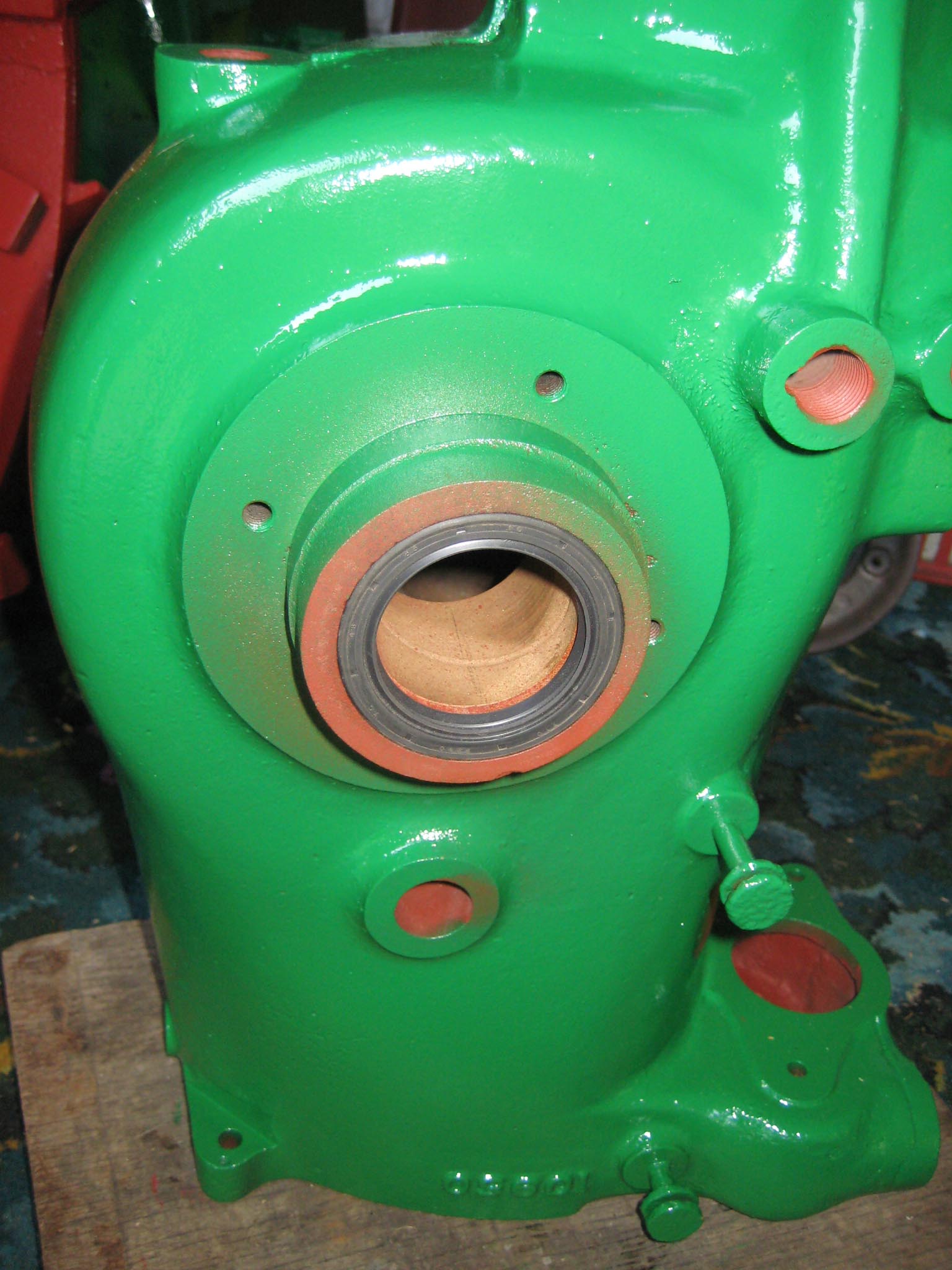
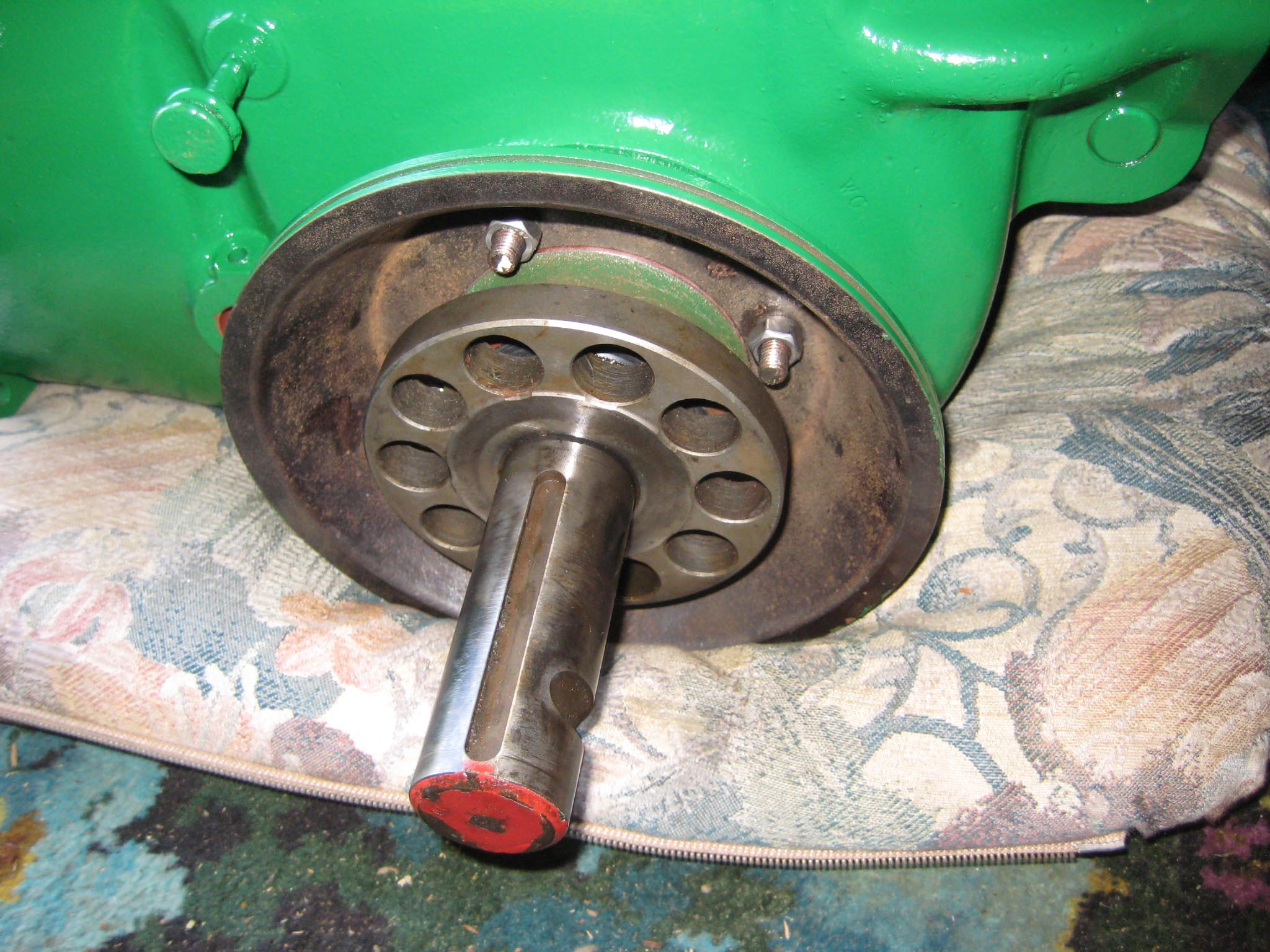
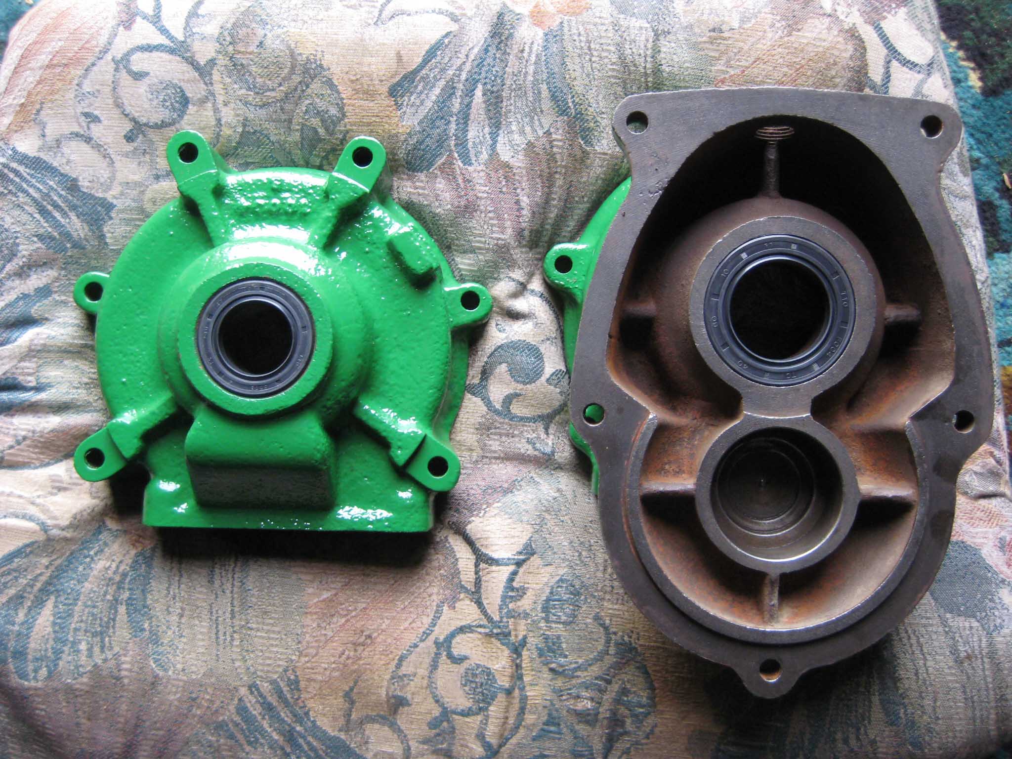
I decided to start with the main gearbox casing. First job was to fit new axle oil seals (Simar 0001). Being of Swiss design, almost everything on the machine is metric, so getting hold of oil seals of the correct size is very straightforward. The axle seals are 65mm outside diameter, 48mm inside diameter and 10mm wide. Next came the M8 studs (Simar 0002) and bowl shaped extension pieces (Simar 0003). The axle components (Simar 0004) were now fitted. I have included a photo of the axle parts fitted together outside of the casing (Simar 0005) as well as inside (Simar 0006 & 7). One item easily missed is the felt washer which fits in a groove machined on the inside of the driven gear sleeves (Simar 0008). I decided not to fit the wheel hubs at this stage, just in case they hindered access when fitting other items and also they would increase the weight of the gearbox making it more difficult to move around.
Attachments:
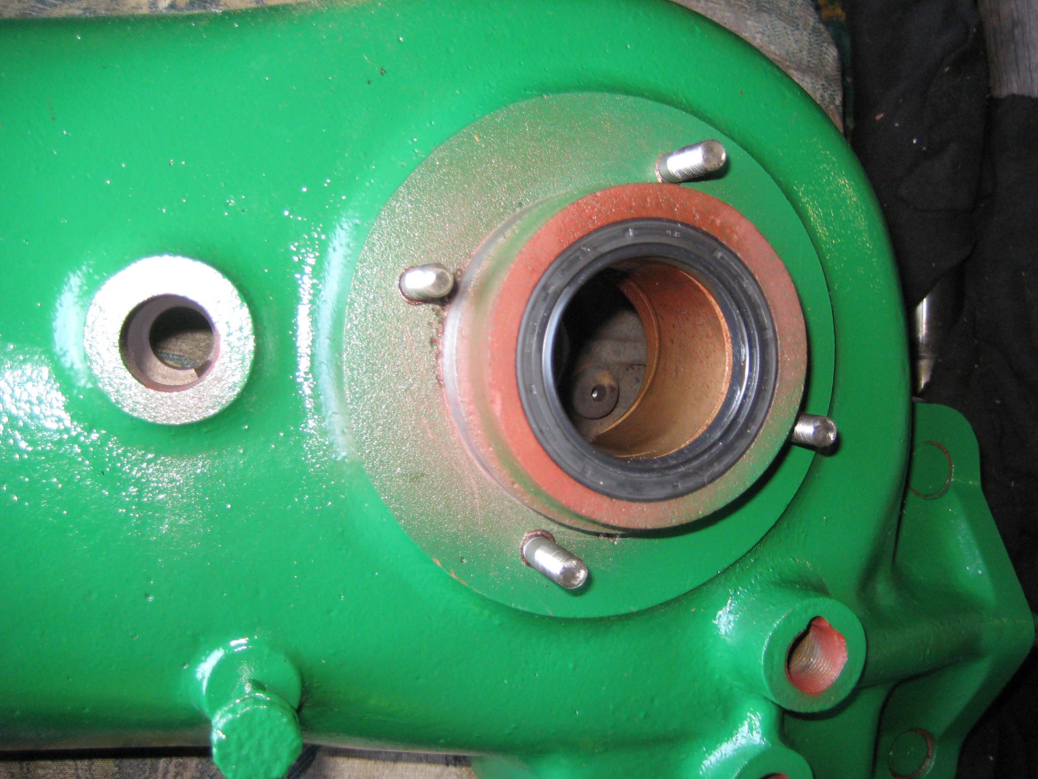
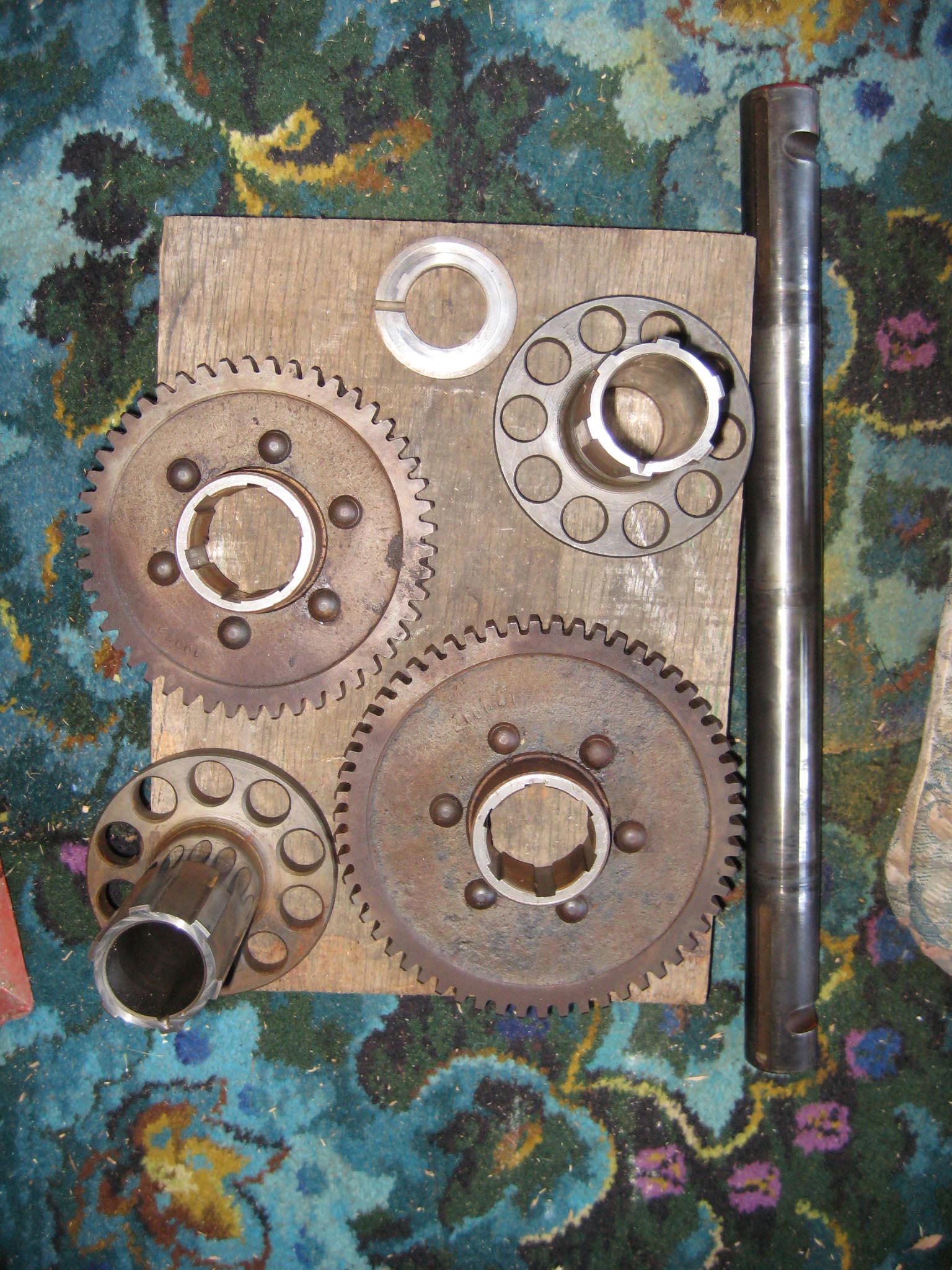
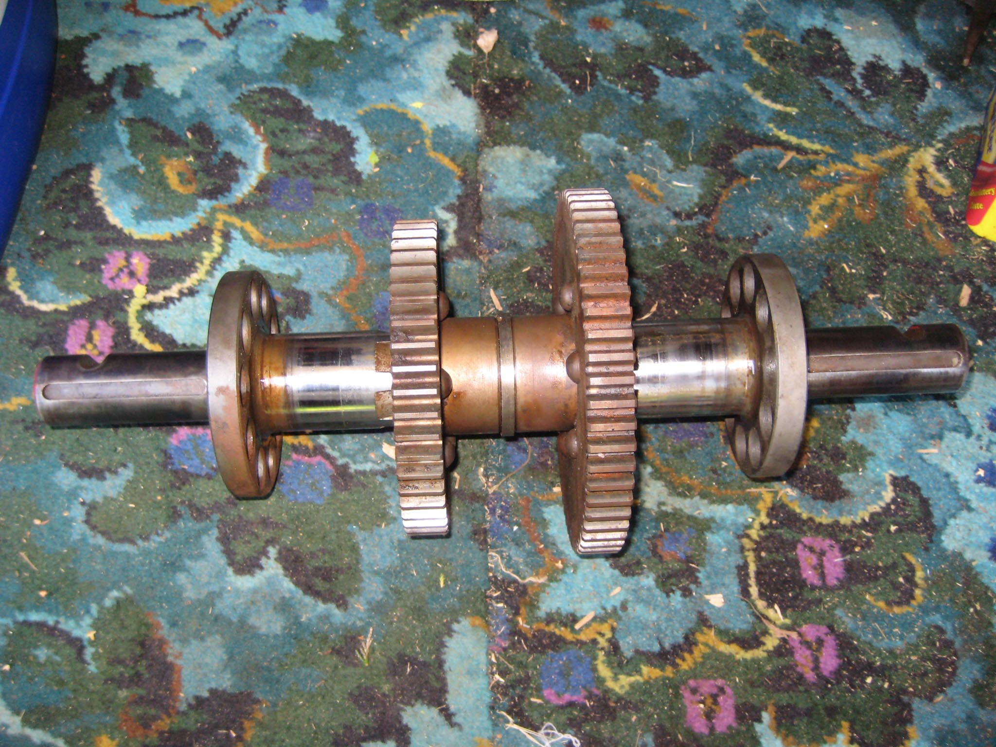
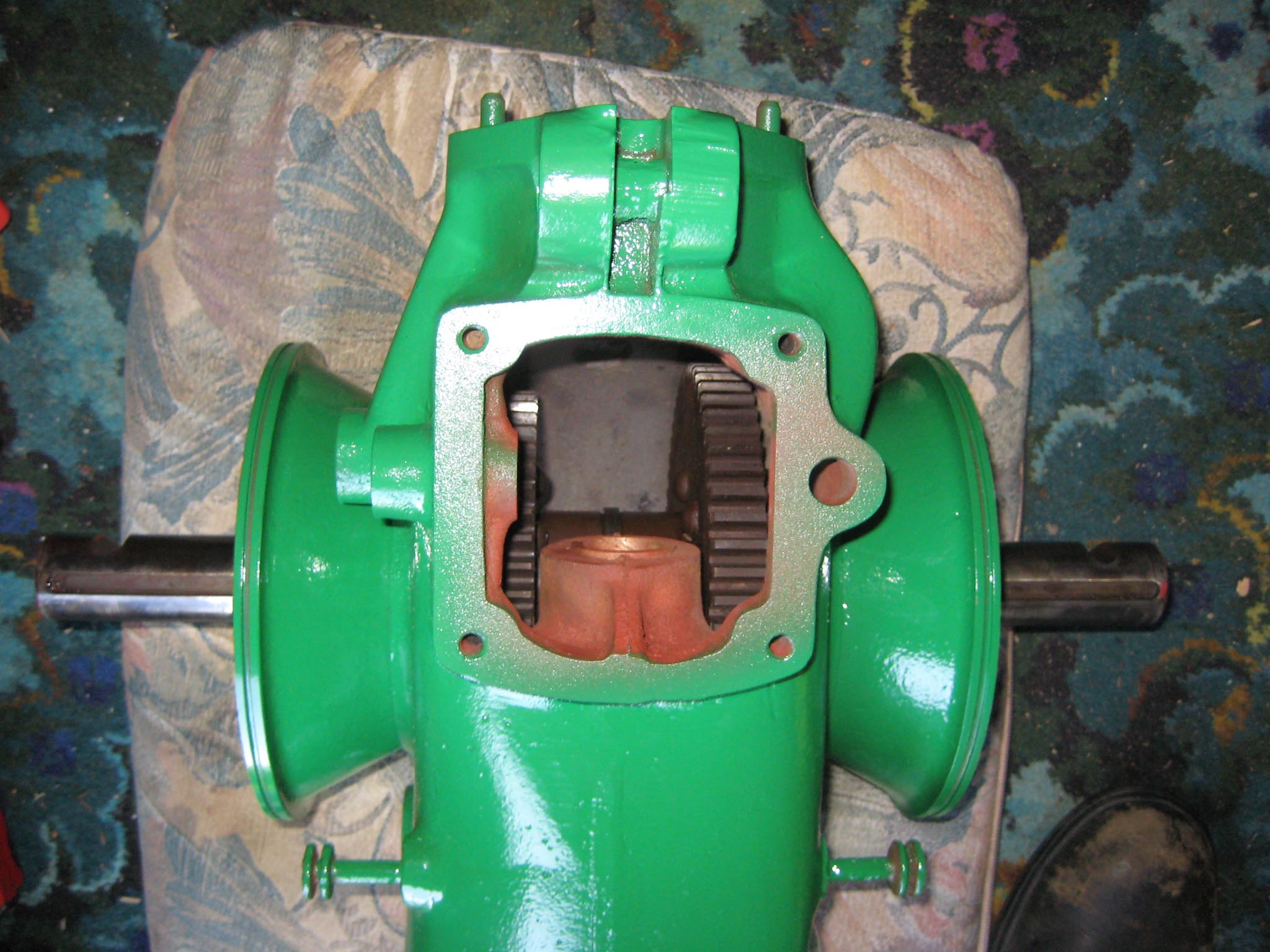
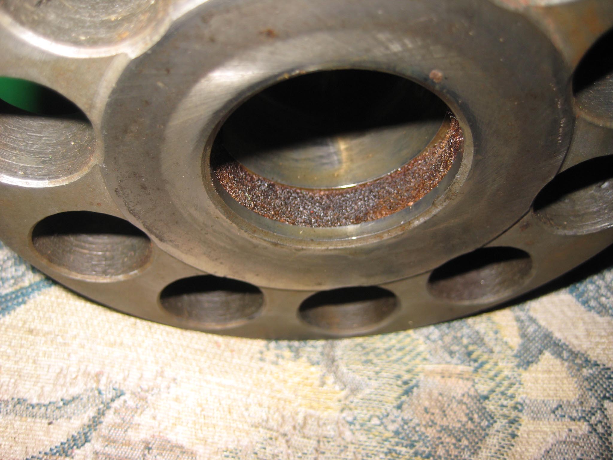
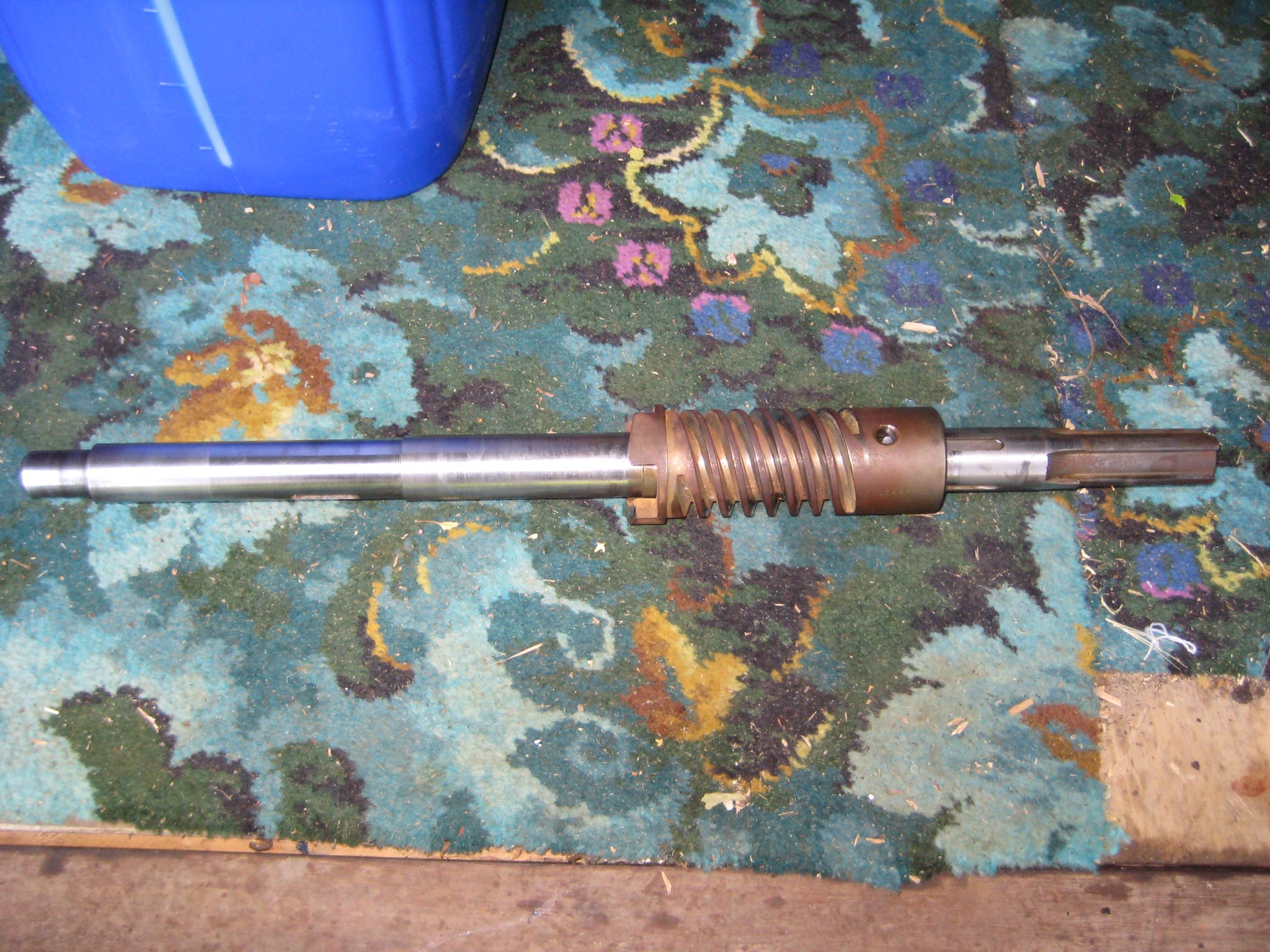
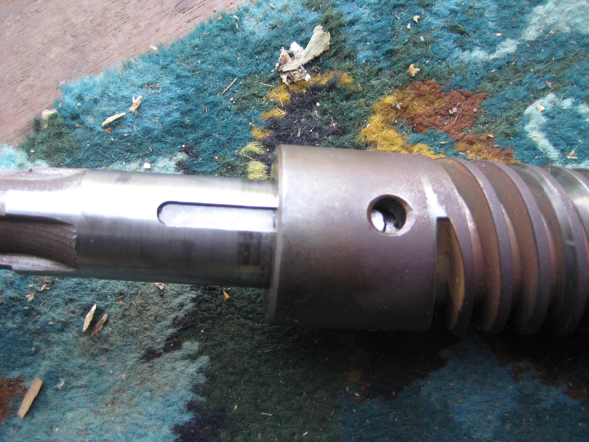
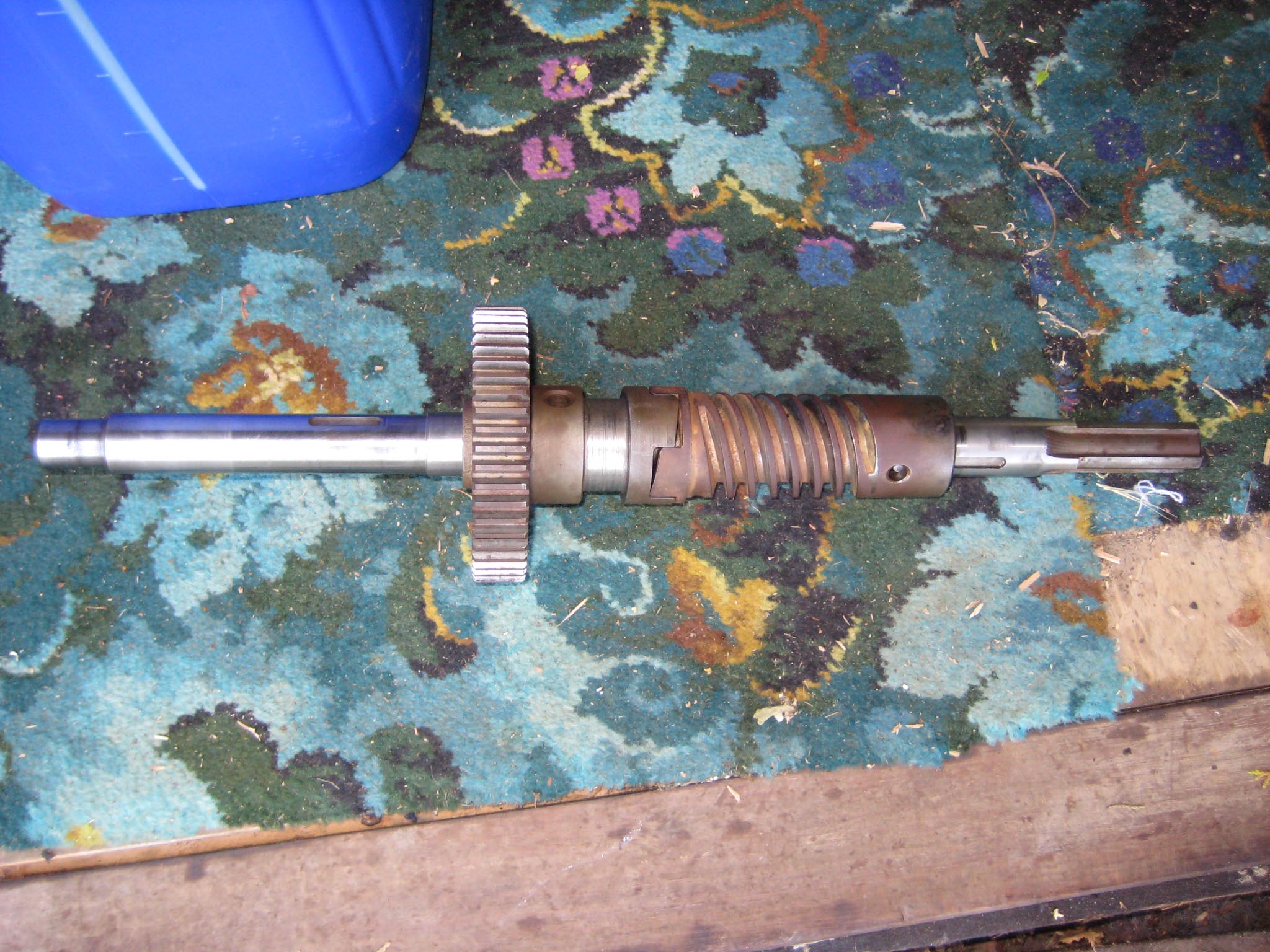
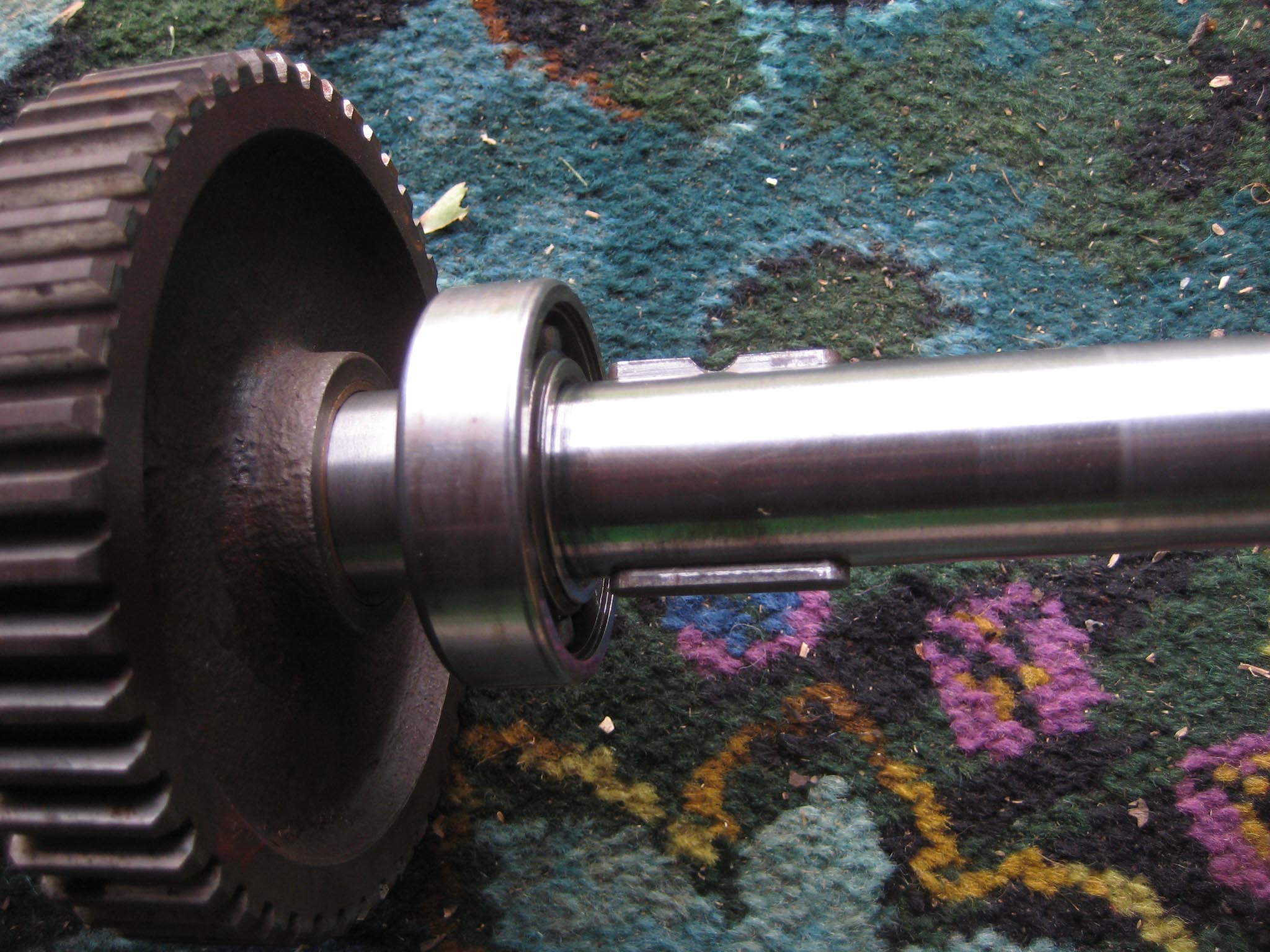
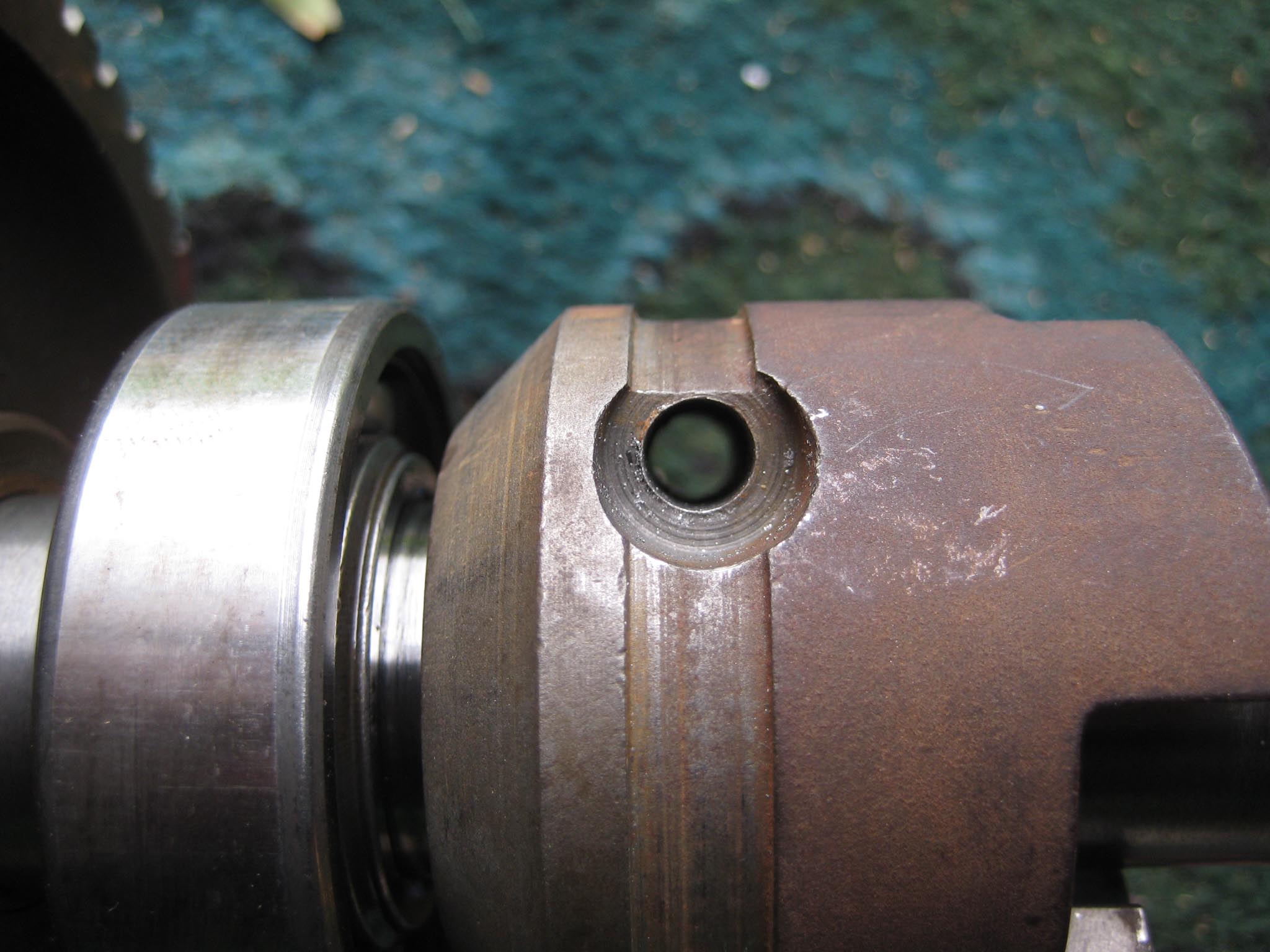
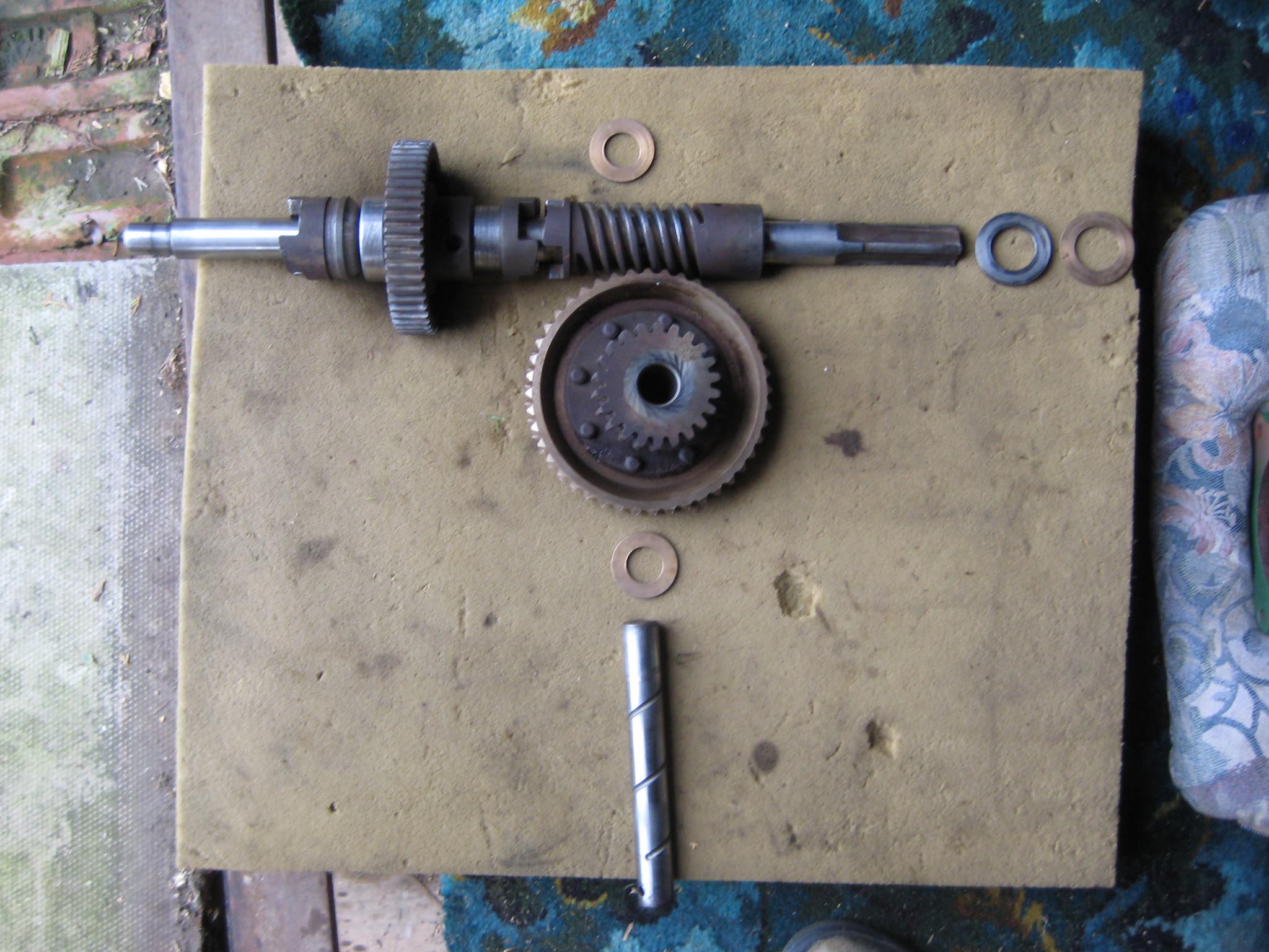
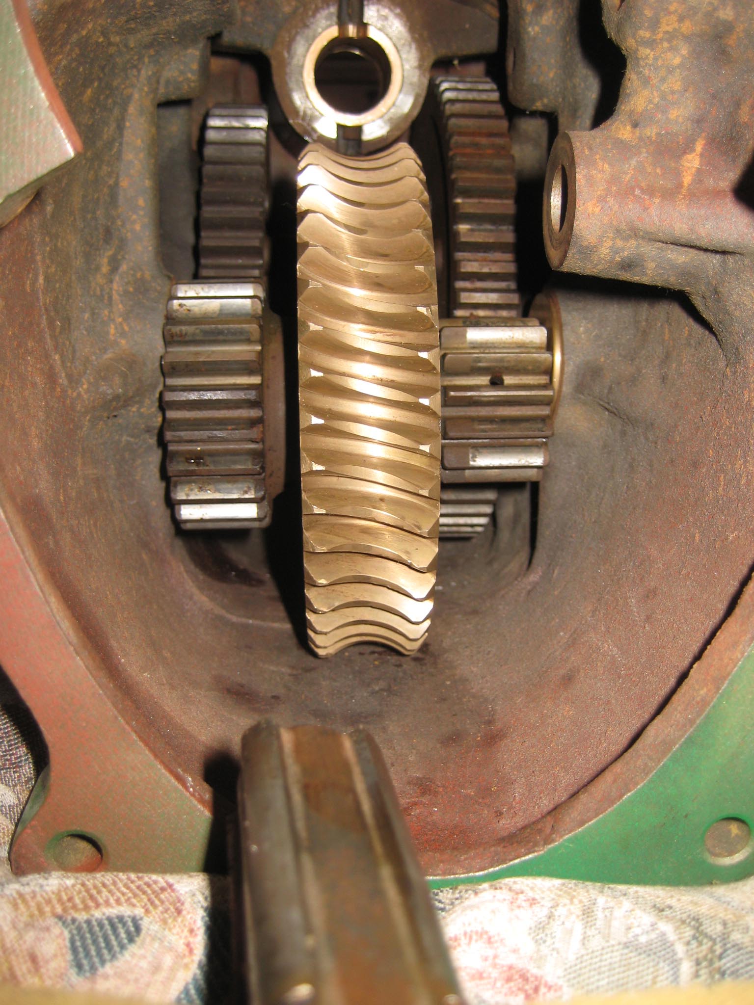
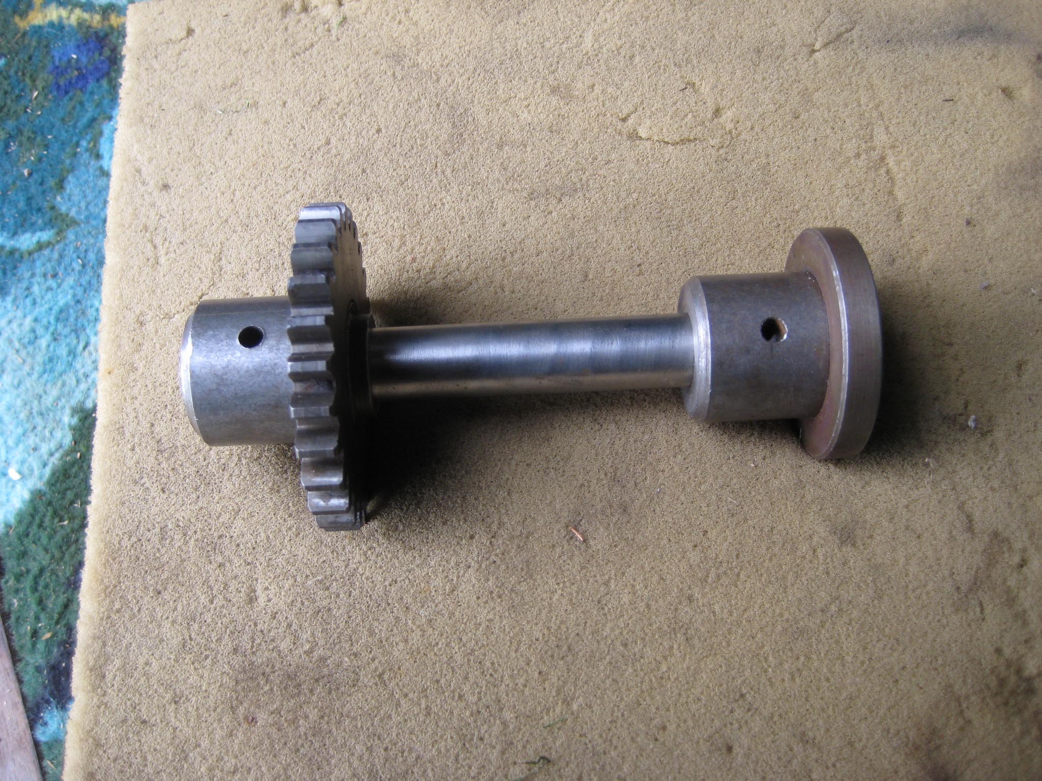
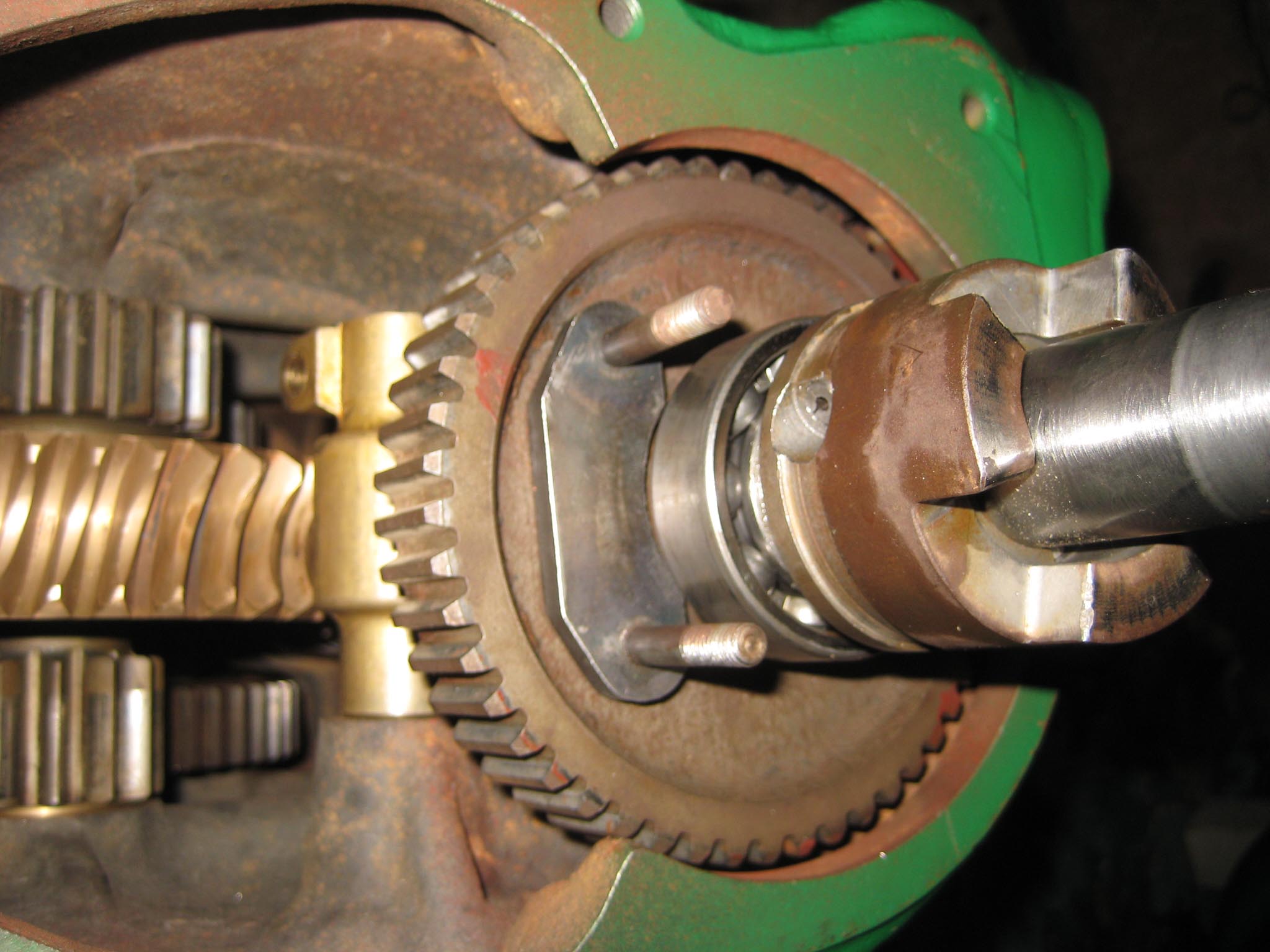
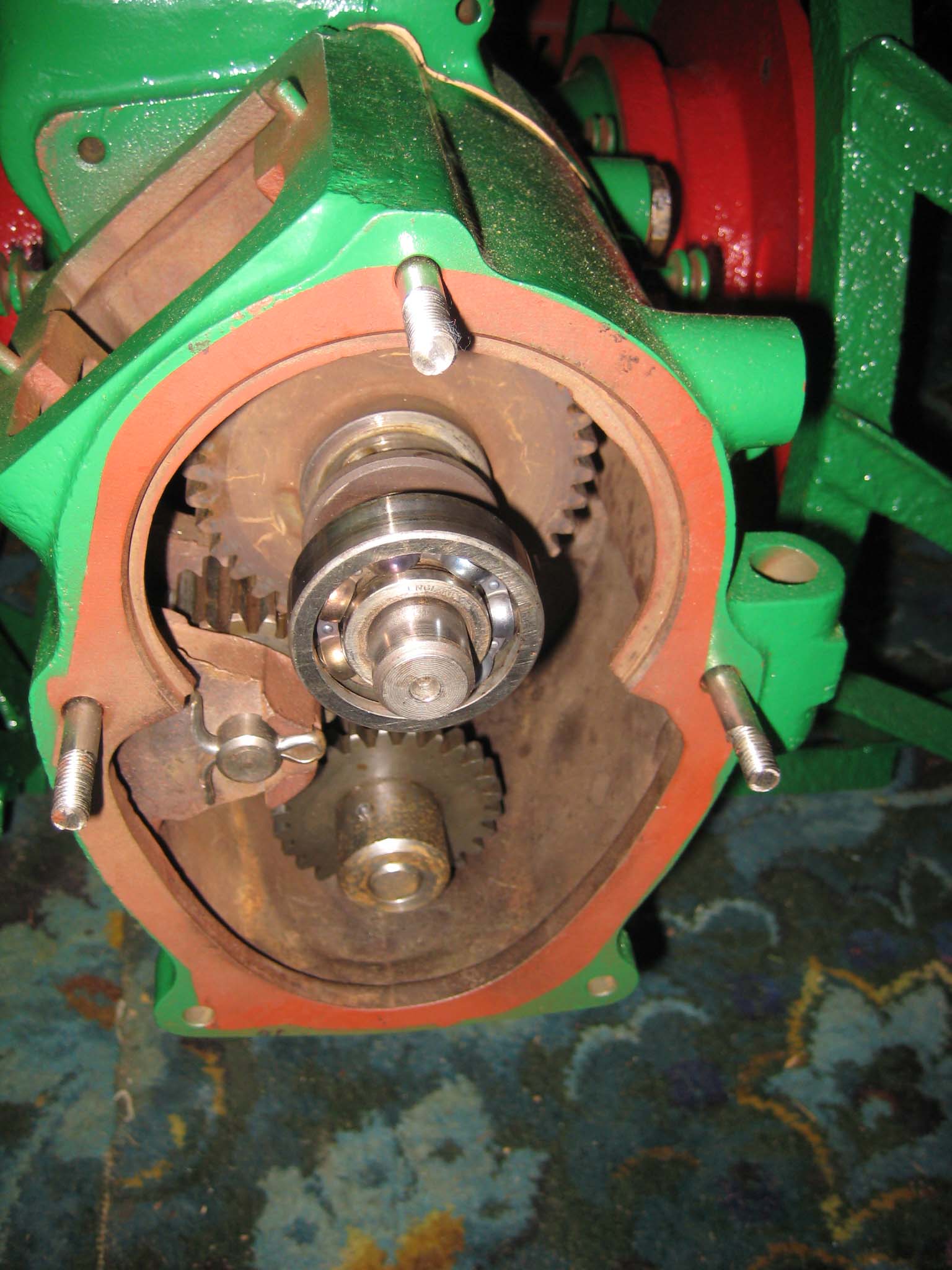
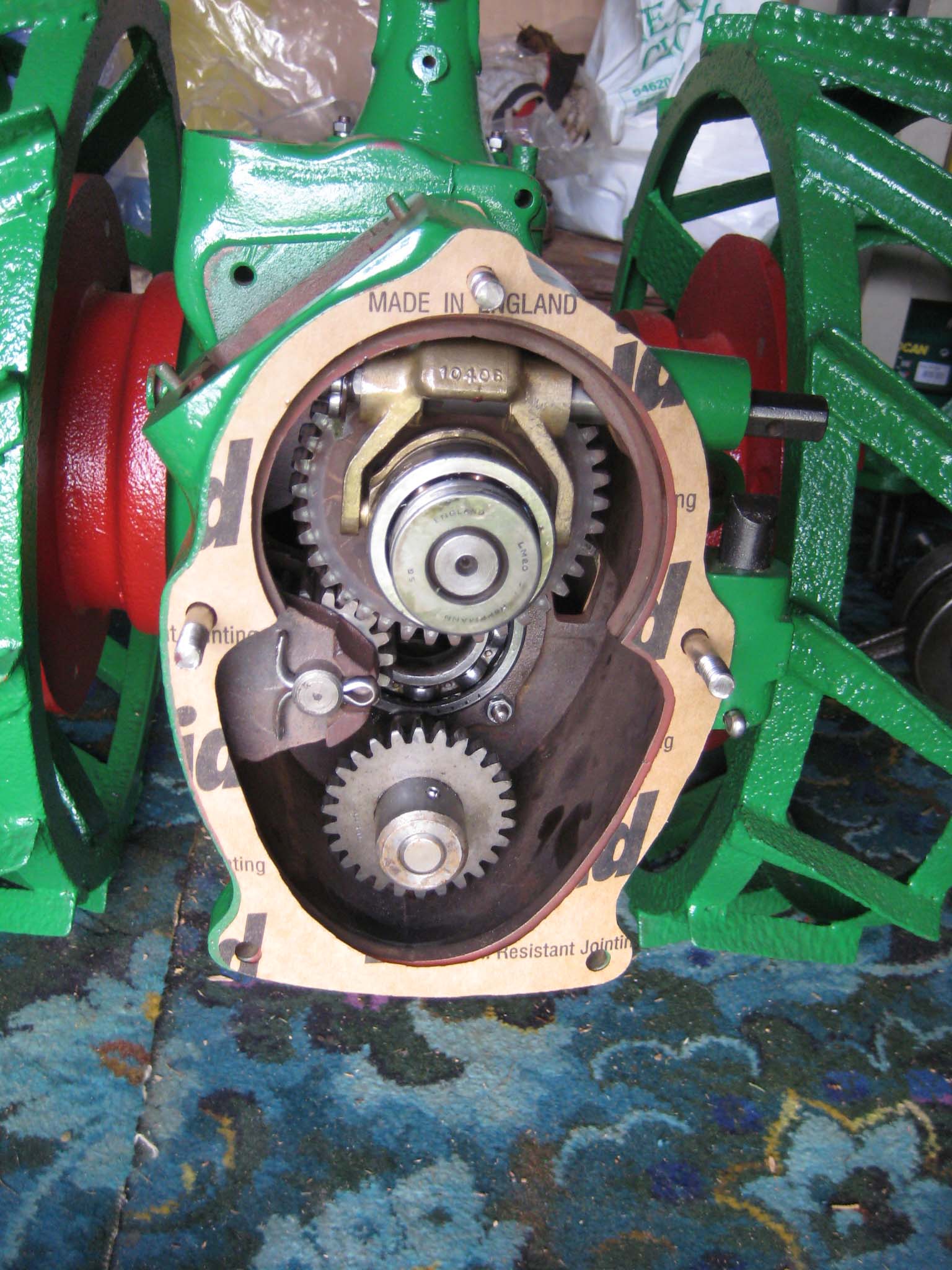
August 31, 2015 at 12:06 pm #14252vhgmcbuddyMemberTo complete the gearbox, the worm wheel assembly and worm drive shaft would need fitting next. Due to the worm drive shaft running all the way through the main gearbox and reverse motion gearbox, re-assembly is a little tricky. It took me a few dry runs to come up with a sequence which would work. I started by assembling the worm drive shaft. Slide the worm along the shaft until it is seated against the collar (Simar 0009). Fit the keys into the keyways on the shaft and then drive them towards and into the worm. There are holes in the worm so you can see when the key is fully home (Simar 0010). Slide the forward motion reduction gear onto the shaft, so that the clutch dogs can mesh together (Simar 0011). Fit the roller bearing so that it is tight against the stepped part of the shaft. I heated the bearing up using an old deep fat fryer which expanded the bearing just enough so that it just slid straight onto the shaft. I find this much easier than trying to drive the bearing into position. The keys for the reverse motion dog go on next. Note that one of the keys has a half moon shape machined into it (Simar 0012). This accomodates the 6 x 30mm roll pin that holds the reverse motion dog in place (Simar 0013). The worm drive shaft is now ready for fitting into the gearbox, but before this can take place, the worm drive gear needs to be inserted into the main gearbox casing first. The parts necessary where laid out to make sure I didn’t forget anything (Simar 0014). The worm drive gear was rolled into the main gearbox casing, making sure that the small gear wheel was on the same side as the low speed driven gear on the axle. One of the distance washers was then inserted between the inside face of the gearbox casing and the worm gear. I partially inserted the worm gear shaft into the gearbox so that it held the distance washer in place (Simar 0015). Fit the distance washer and thrust washer to the worm drive shaft and insert through the bronze bush at the rear of the gearbox. Now lift the worm gear up so that it is meshed with the worm. The shaft holding the distance washer in place can be pushed all the way through the worm gear. Fit the distance washer to the opposite side of the worm gear and continue pushing the worm gear shaft all the way through until it emerges from the casing. Note that this shaft has a hole through one end which must align with a corresponding hole in the gearbox casing. The shaft is then held in place by a 6 x 50mm roll pin.
Attachments:
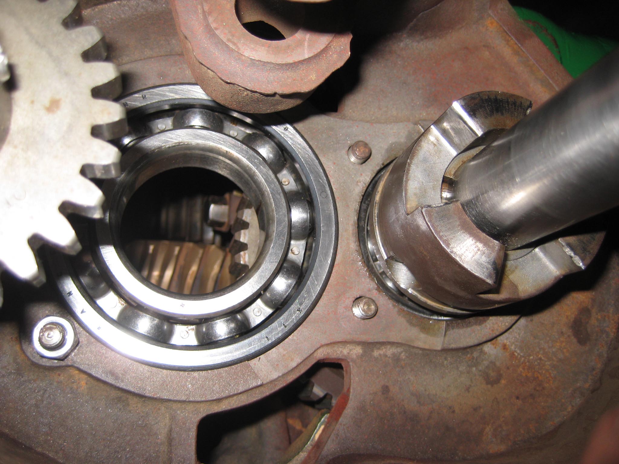
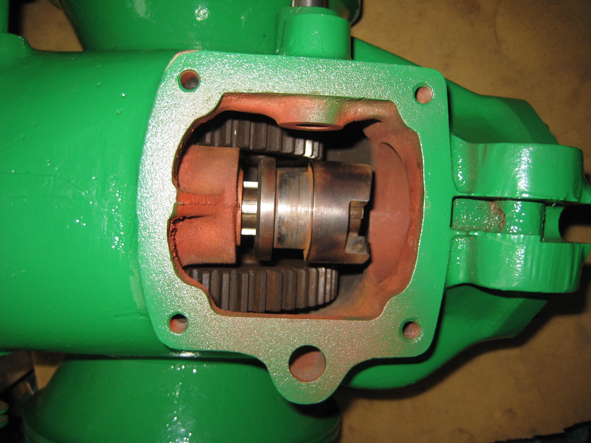
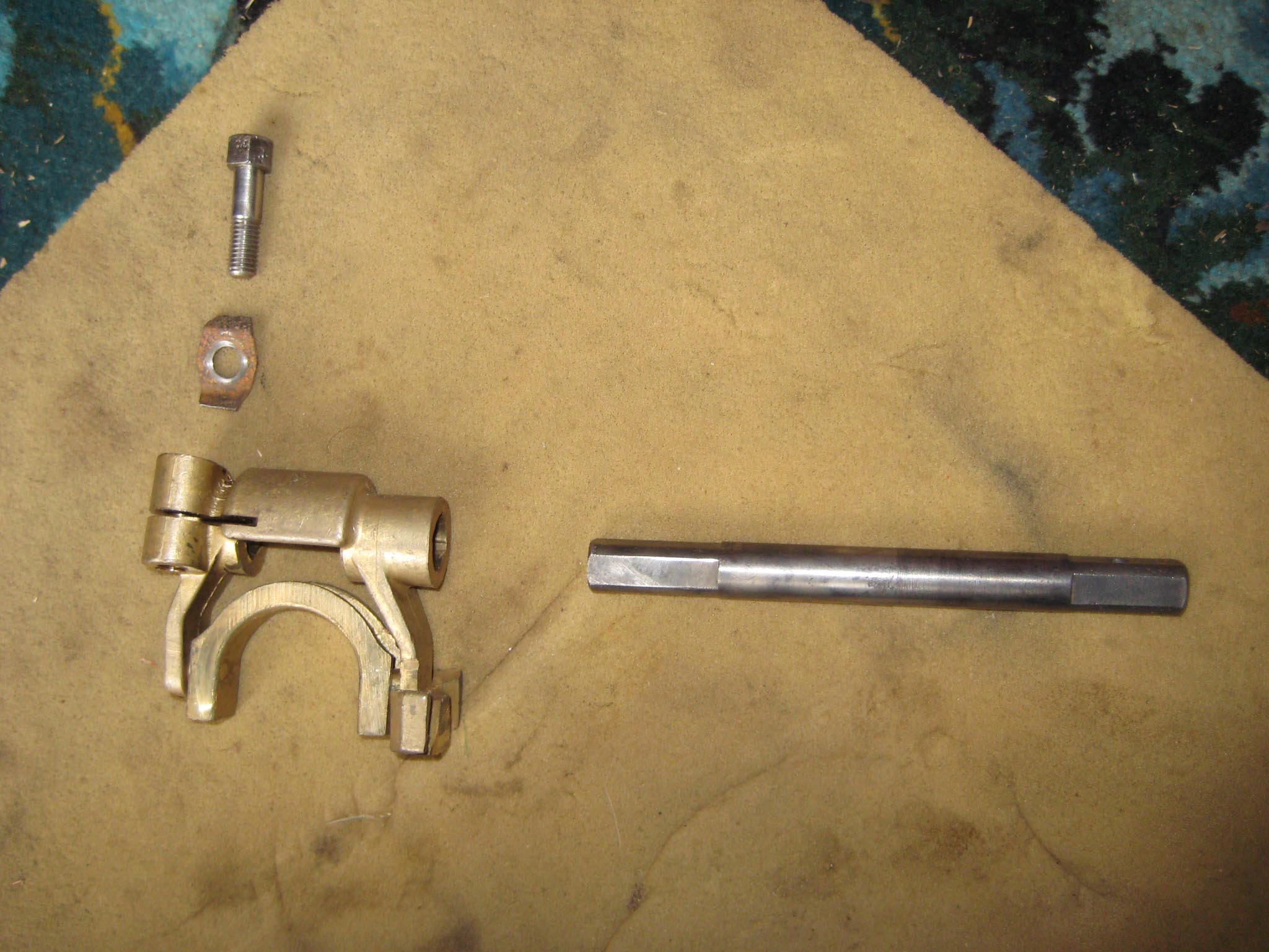
August 31, 2015 at 12:11 pm #14260vhgmcbuddyMemberNext items to be fitted were the forward motion clutch fork, collar and shaft (Simar 0016). The clutch collar fits into a machined groove on the forward motion reduction gear (Simar 0017). This is easier with the gearbox stood on it’s rear end, pointing vertically upwards, otherwise gravity makes the collar drop out!! The hole for the clutch shaft can be seen just to the right of the collar. Slide the clutch fork into the collar and then insert the shaft through the gearbox casing into the clutch fork. The shaft is square at both ends, with the outside end being the one which has a hole drilled through it (Simar 0018). It is very important that the shaft is aligned as shown in the photo, otherwise the lever which fits onto the outer end of the shaft will be in the wrong orientation and won’t connect up with the control rods on the handlebars. The clutch fork clamps to the inner end of the shaft using a bolt complete with locking tab (Simar 0019).
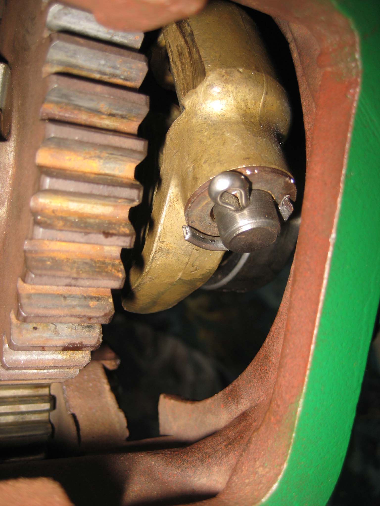
The reverse motion gearbox can now be prepared for fitting. Fit the rear crankshaft roller bearing into the casing. This is held in place by thick washers and bolts (Simar 0020 & 21). The oil flinger assembly is fitted next (Simar 0022), the drive gear and flinger disc being held to the shaft by 5 x 34mm roll pins.Attachments:
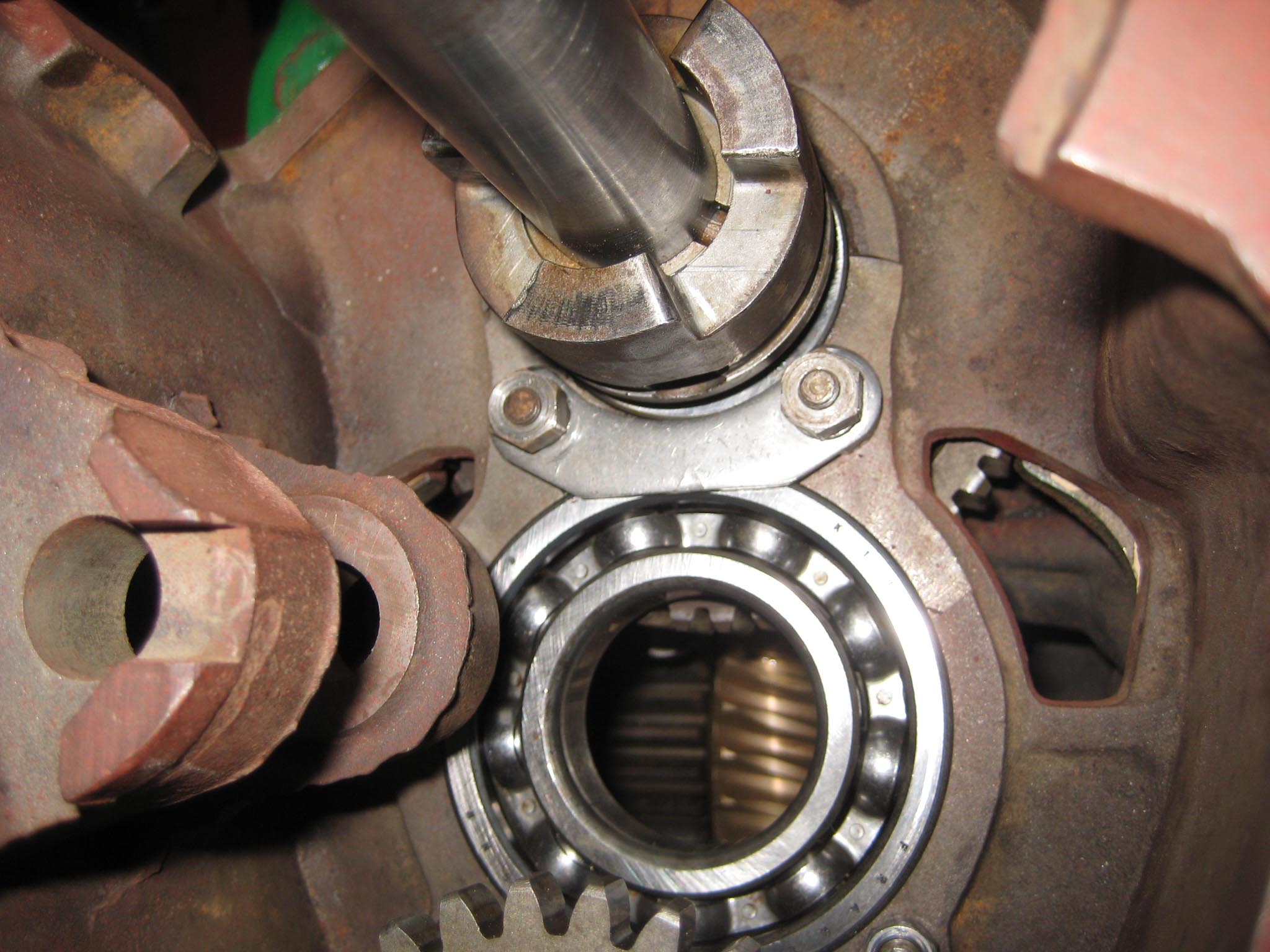
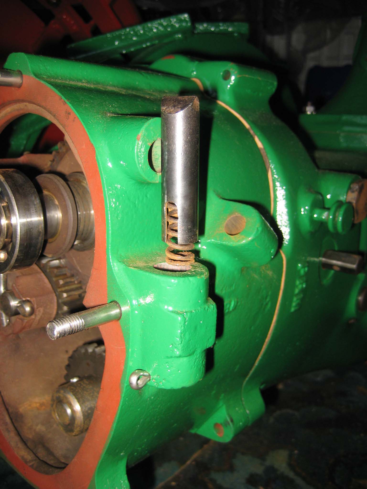
August 31, 2015 at 12:17 pm #14268vhgmcbuddyMemberBefore the reverse motion gearbox can be attached to the main gearbox, fit the three long M8 studs into the main gearbox and then the paper gasket (Simar 0023). Place the roller bearing securing bracket loosely onto the forward motion reduction gear, making sure that the gear is out of mesh with the worm, i.e. is at it’s furthest forward position (Simar 0024). Now for the tricky bit!! Lower the reverse motion gearbox, so that the two studs on the roller bearing securing bracket begin to protrude through the two holes in the casing (Simar 0025). As the securing bracket isn’t attached to anything, a degree of patience is required to joggle it into location. Fortunately, the rear crankshaft roller bearing has a sufficiently large enough inner diameter to allow access for a couple of fingers!! A further complication is that the casing has to fit onto the bearing on the worm drive shaft which is a press fit. Mine went on with a few well placed blows with a rubber mallet. Once the reverse motion gearbox casing is in position, place the gearbox so that it is sat just past horizontal, with the front lower than the rear. Gravity will then keep the roller bearing securing bracket in position while the inner securing plate and nuts are fitted (Simar 0026). Final bits to go in are the safety spring for the reverse motion dog (Simar 0027) and reverse motion pinion gear (Simar 0028 & 29) which is simply held in place with a couple of 6 x 30mm split pins. There are a few more items which need to be fitted onto to the worm drive shaft, but I decided to leave those off until the engine is ready to be fitted. Final job for the day was to fit the forward motion clutch locking plunger, which simply pushes into a hole in the main gearbox casing (Simar 0030). Note that the photo does not show the fibre washer which fits to the threaded plug.
Attachments:
August 31, 2015 at 4:36 pm #14277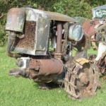 charlieKeymaster
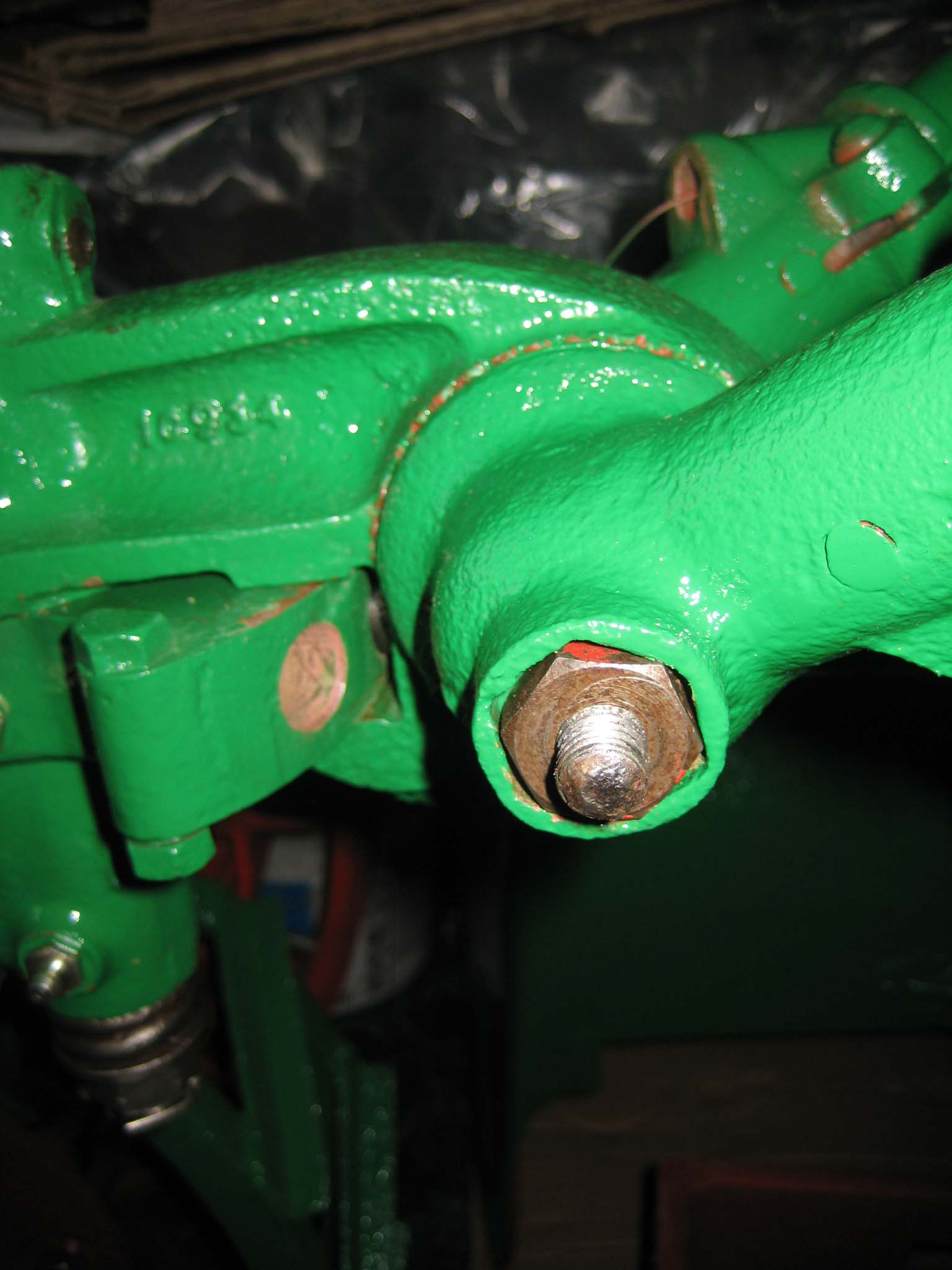
Excellent photos and description. I see the gearbox casing has the letters PRM cast into it; from my research going through the Geo Monro drawings at MERL PRM stands for Percy Riley Motors of Coventry. They carried out avariety of work for Geo Monro and some drawings have PRM on them, there is also a document detailing parts made by PRM, and others supplied by Geo Monro and finished by PRM.
August 31, 2015 at 5:21 pm #14278vhgmcbuddyMemberThanks Charlie. Was wondering who’s foundry mark PRM was. The reverse gearbox casing is also marked PRM. I always wonder how many other companies were involved in supplying parts to the various machinery manufacturers, particularly if any of them still exist. All adds detail to a machines history.
September 1, 2015 at 3:13 pm #14279 hillsiderParticipant
I saw PRM thought I have seen that somewhere myself, it was many moons ago on a marine gearbox fitted to a work boat. So I looked them up to see if they are still around and it seems as though they are, see the attached link.
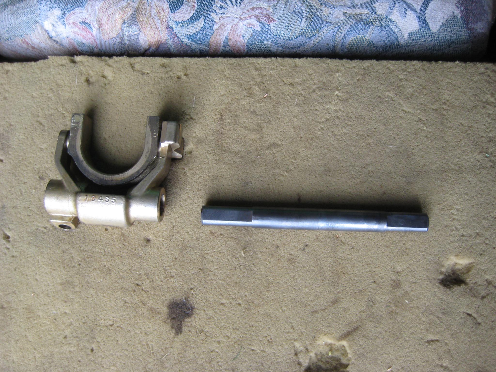
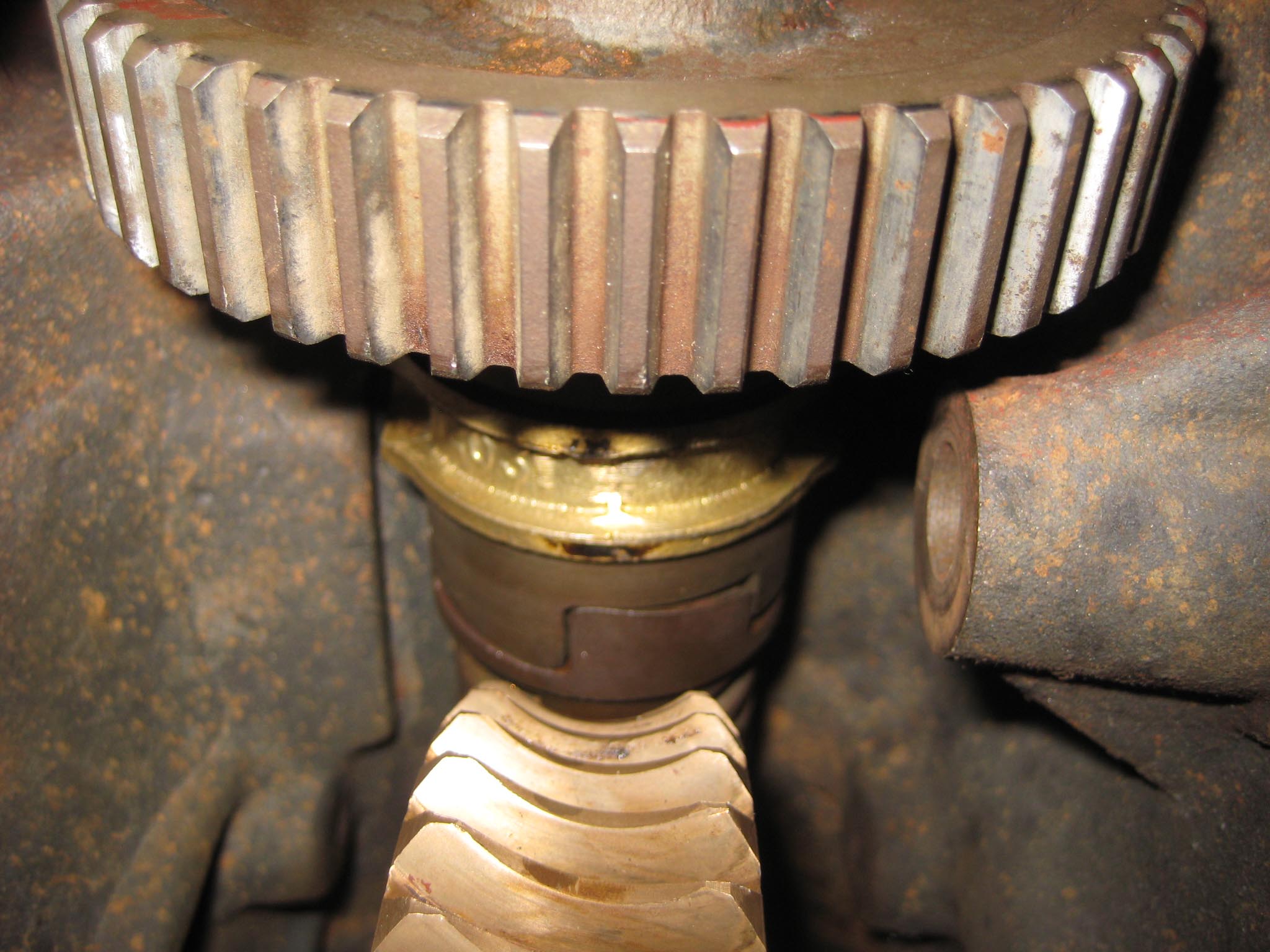
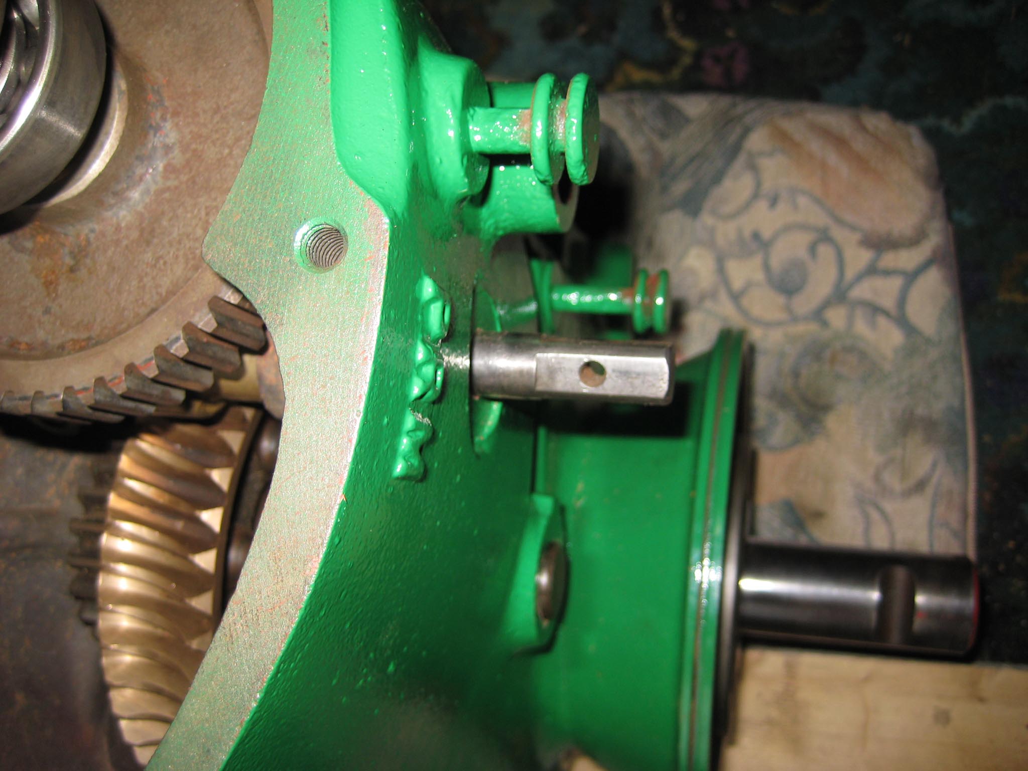
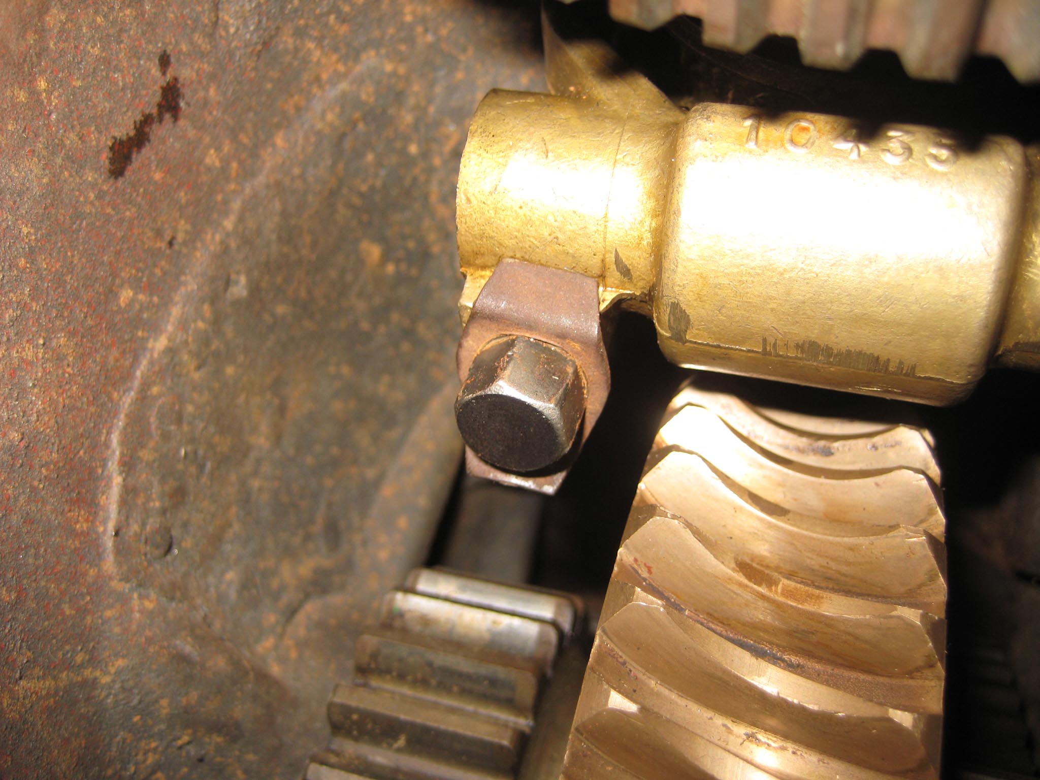
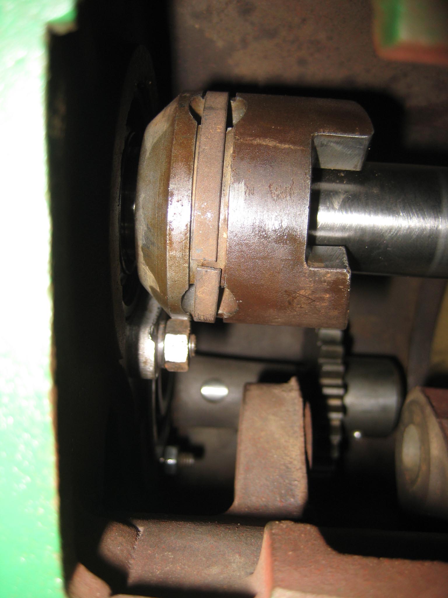
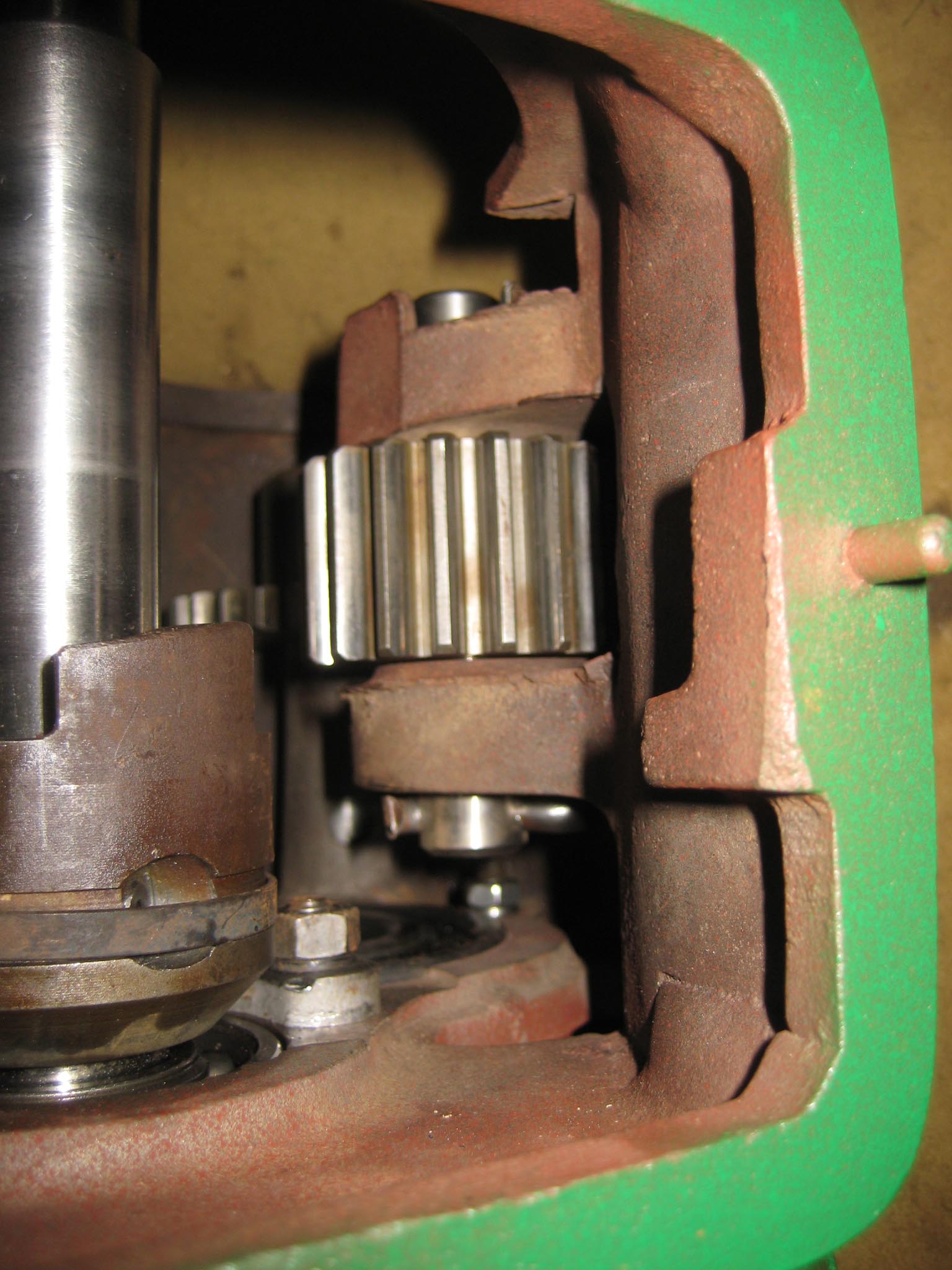
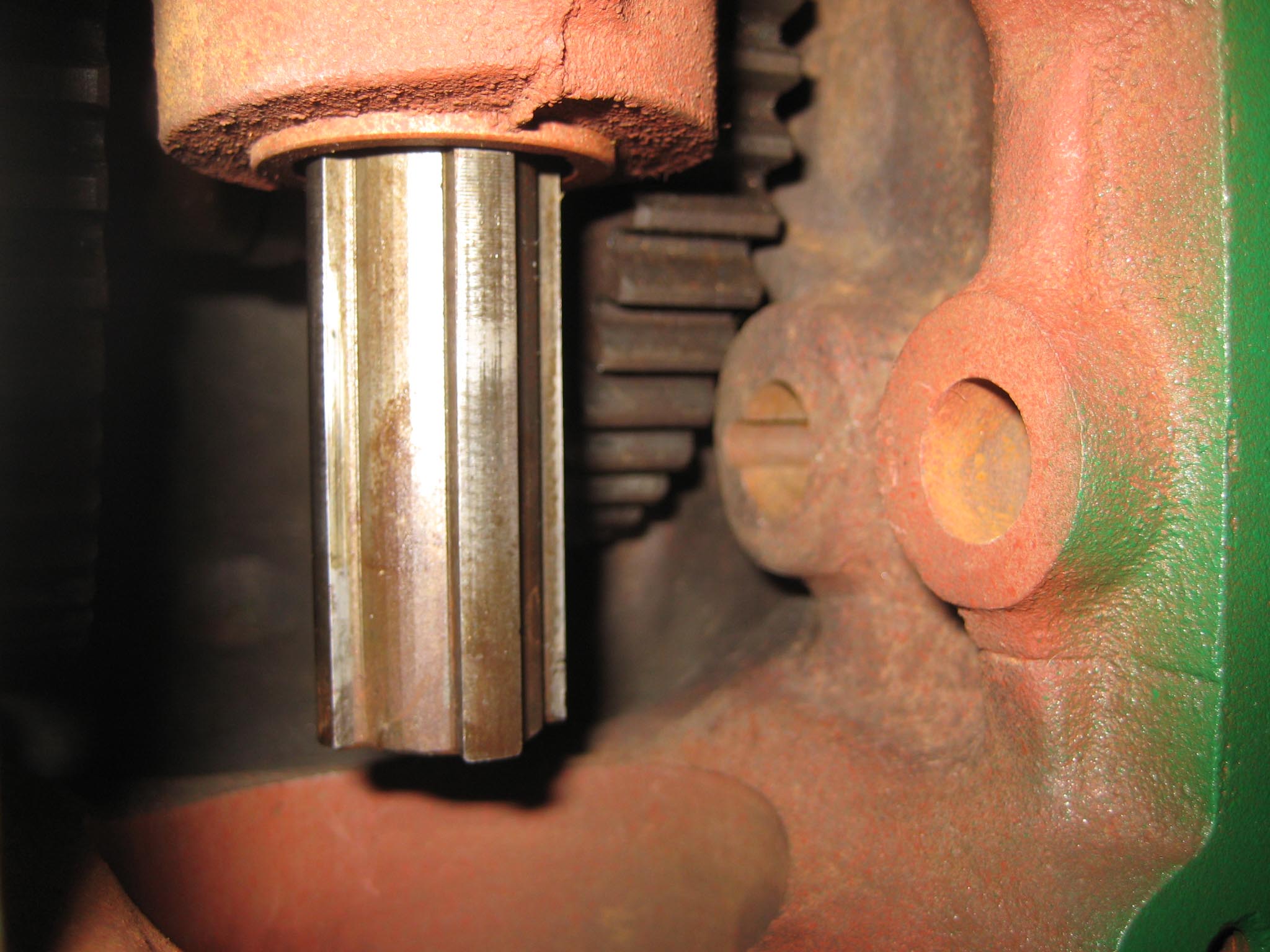
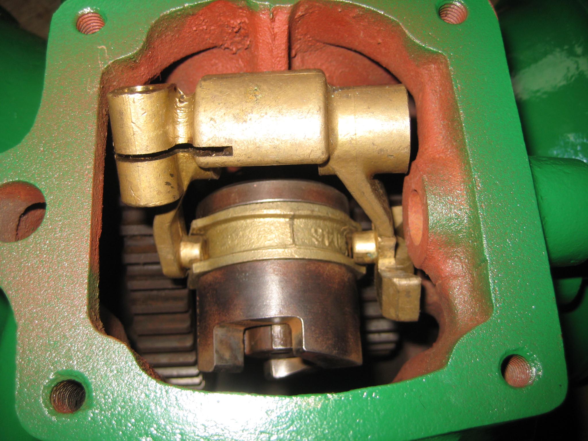
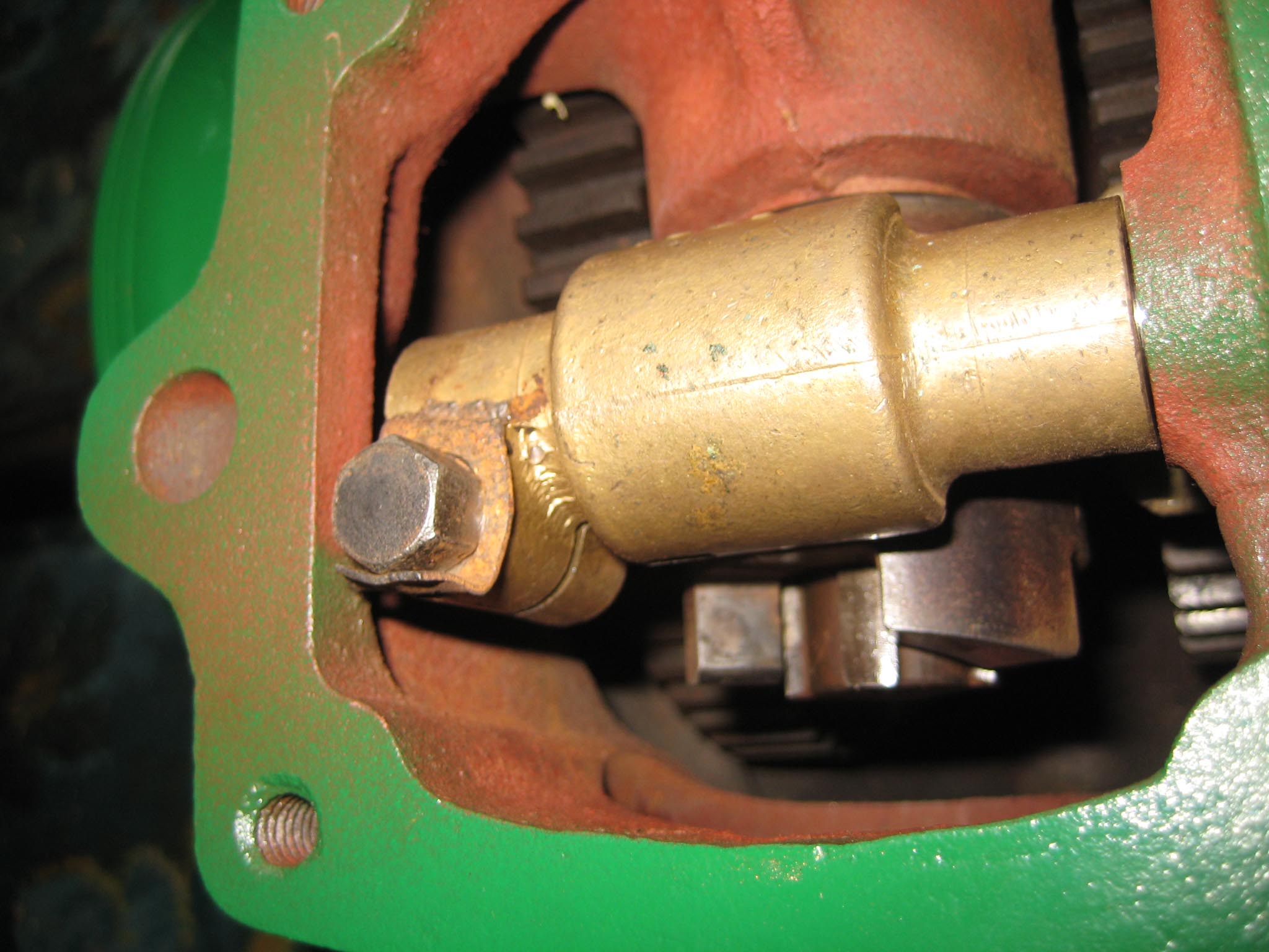
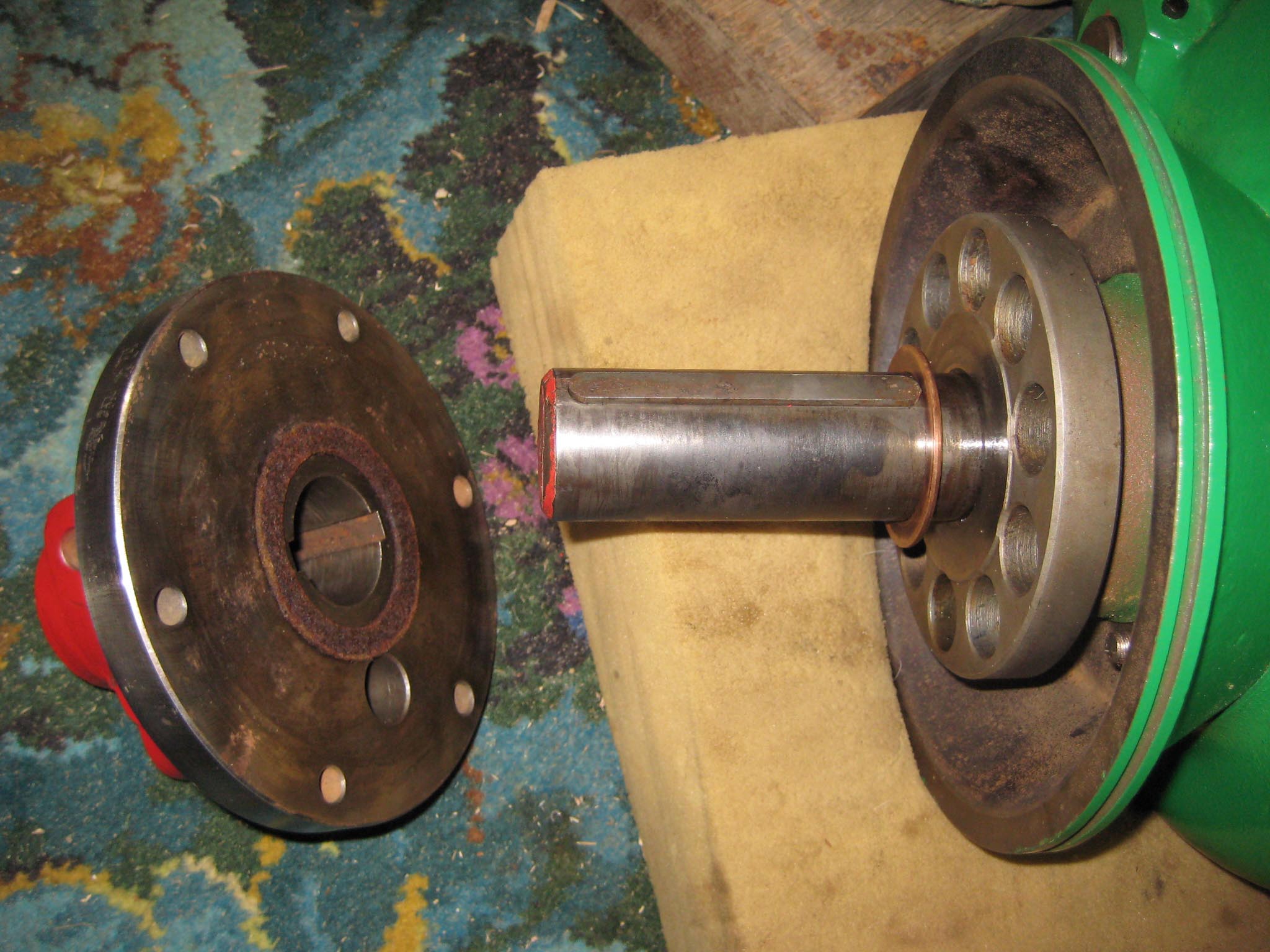
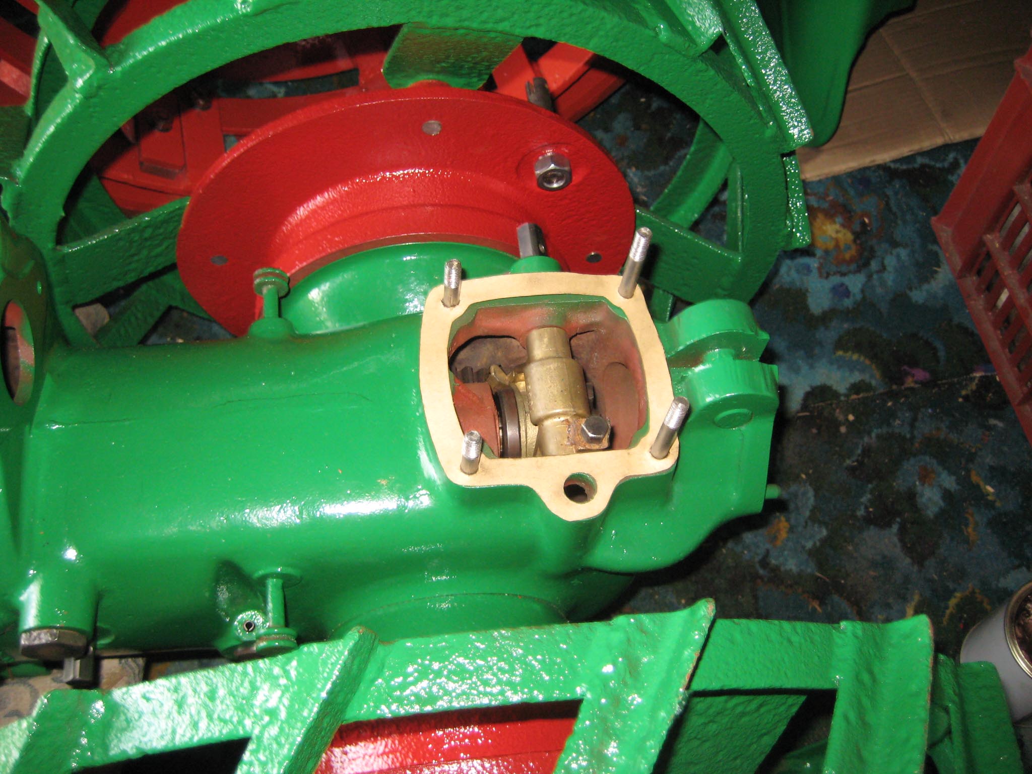
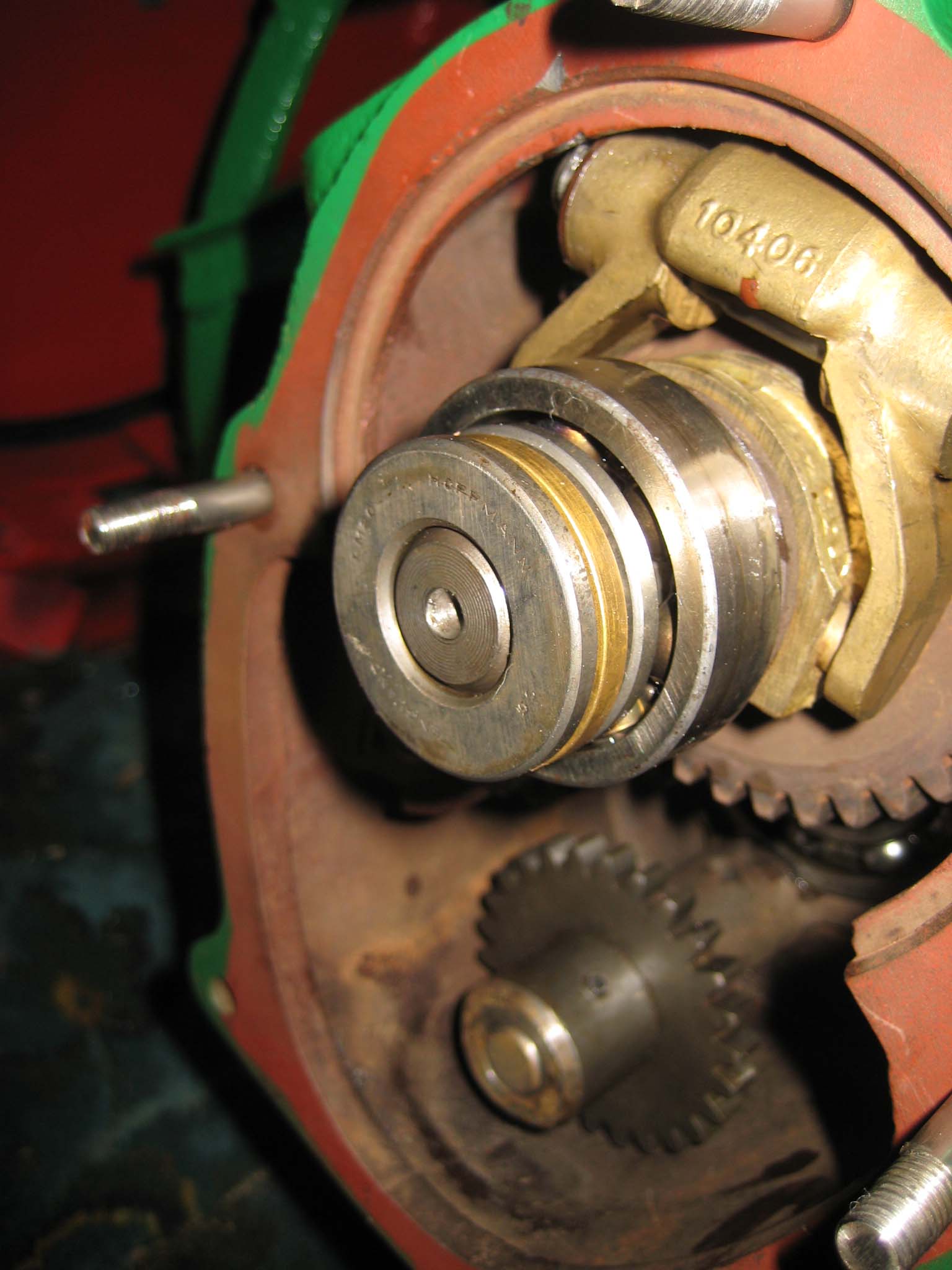
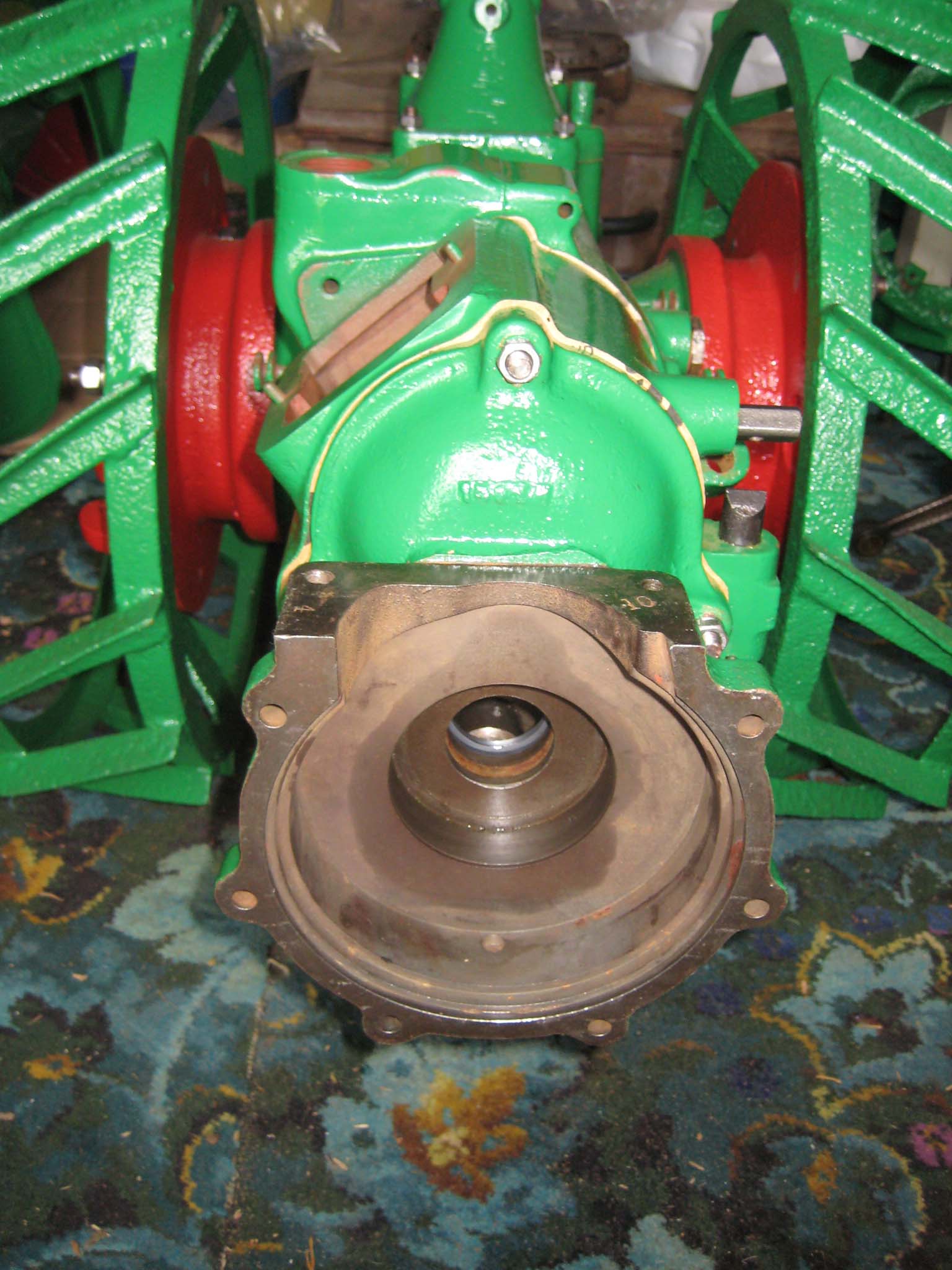
September 5, 2015 at 5:40 pm #14321vhgmcbuddyMemberToday got off to a bad start as I realised the locking plunger for the miller clutch couldn’t be fitted from the outside of the main gearbox, as the hole is blocked by the axle bowl extensions (Simar 0031). To make matters worse, the rear end of the worm drive shaft blocks access from inside the gearbox (Simar 0032). So, the axle bowl extensions had to be removed. I am glad I hadn’t also fitted the wheel hubs!! With the locking plunger fitted, the sliding dog for the miller drive was slid onto the end of the worm drive shaft (Simar 0033). The miller clutch parts (Simar 0034) could now be installed, starting with the clutch fork collar and clutch fork (Simar 0035). The clutch fork shaft was slid into position, making sure that outer end with the hole in for a roll pin was correctly orientated (Simar 0036), shown at the very top of this picture. The clutch fork is clamped onto the shaft using a bolt and locking tab (Simar 0037).
Attachments:
September 5, 2015 at 5:55 pm #14329vhgmcbuddyMemberI next prepared the hubs for fitting onto the axle by installing the locking mechanism for the large pins which slot through the hubs into the driven gear sleeves (Simar 0038 & 39). Before the hubs can be fitted to the axle, the wheel flanges need to be installed (Simar 0040). Slide the Bronze washer onto the axle and then fit the two long keys into their keyways. Before sliding the hub onto the axle, make sure the felt washer is fitted into the machined groove on the back face of the hub (Simar 0041). At both ends of the axle shaft is a half moon shaped groove. This lines up with a hole in the hub (Simar 0042). An M12 x 75 bolt fits through this hole, making sure that the securing tab for the hub plug chain is fitted under the bolt head (Simar 0043).
Attachments:
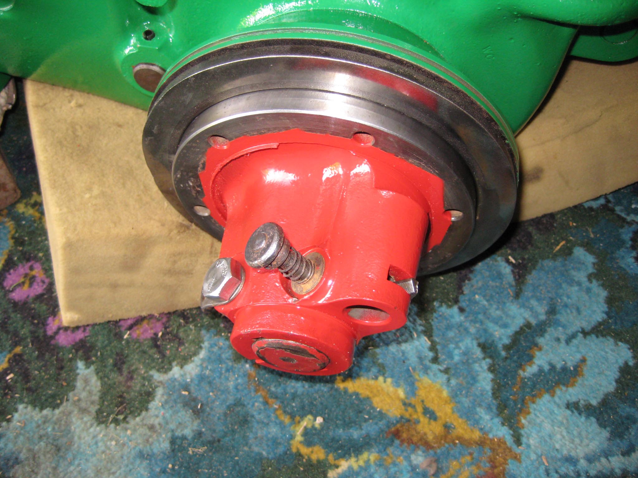
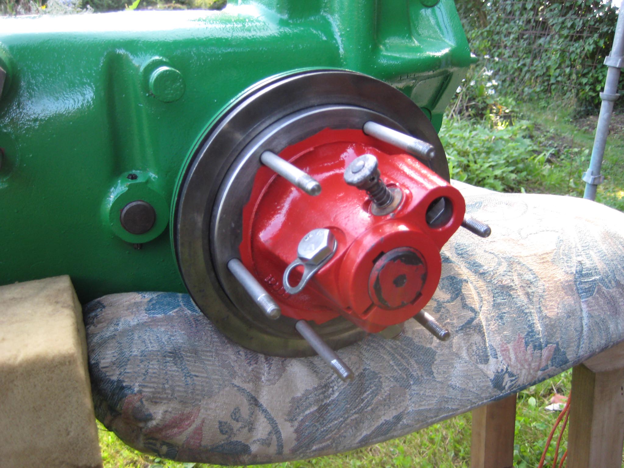
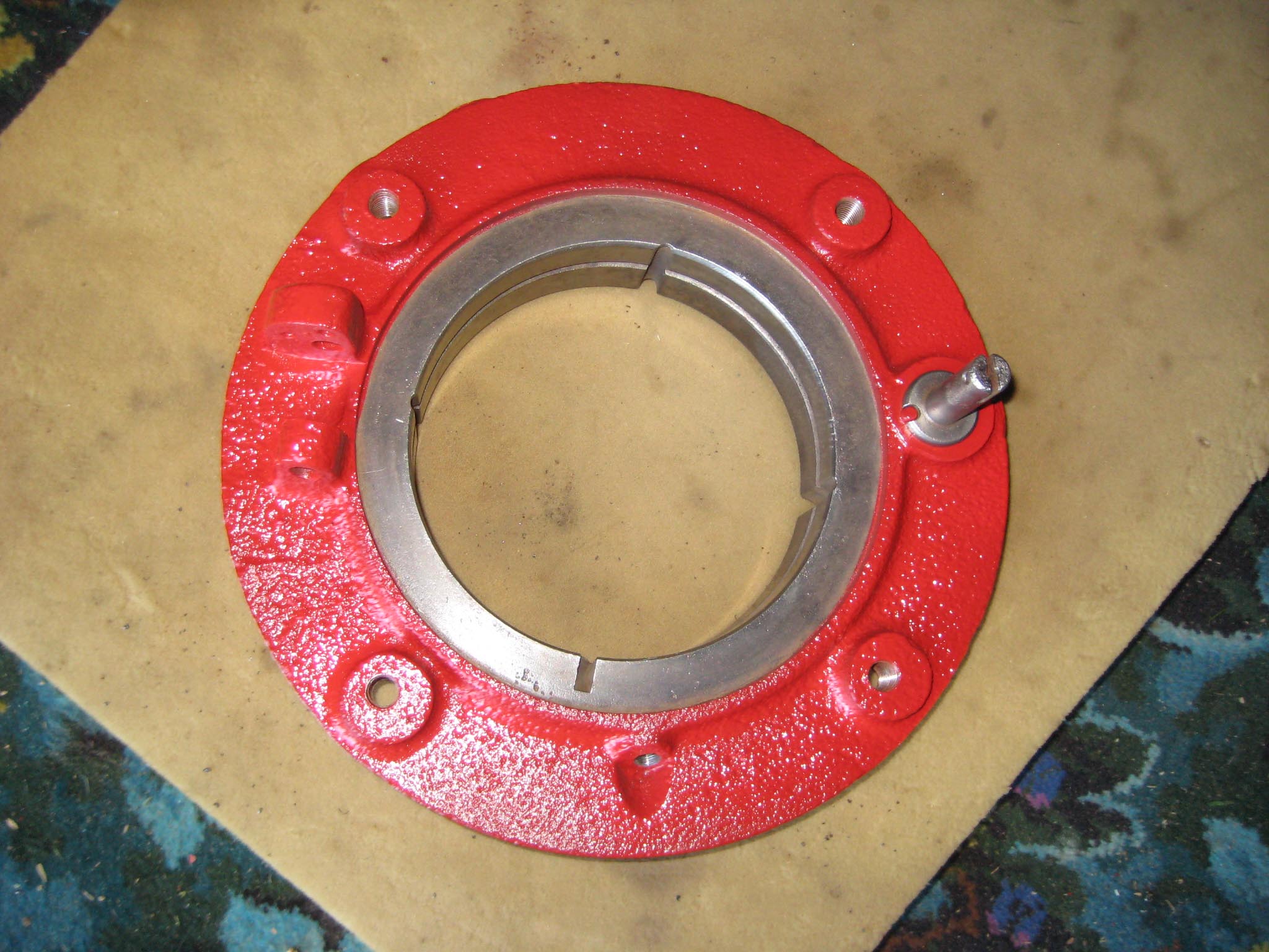
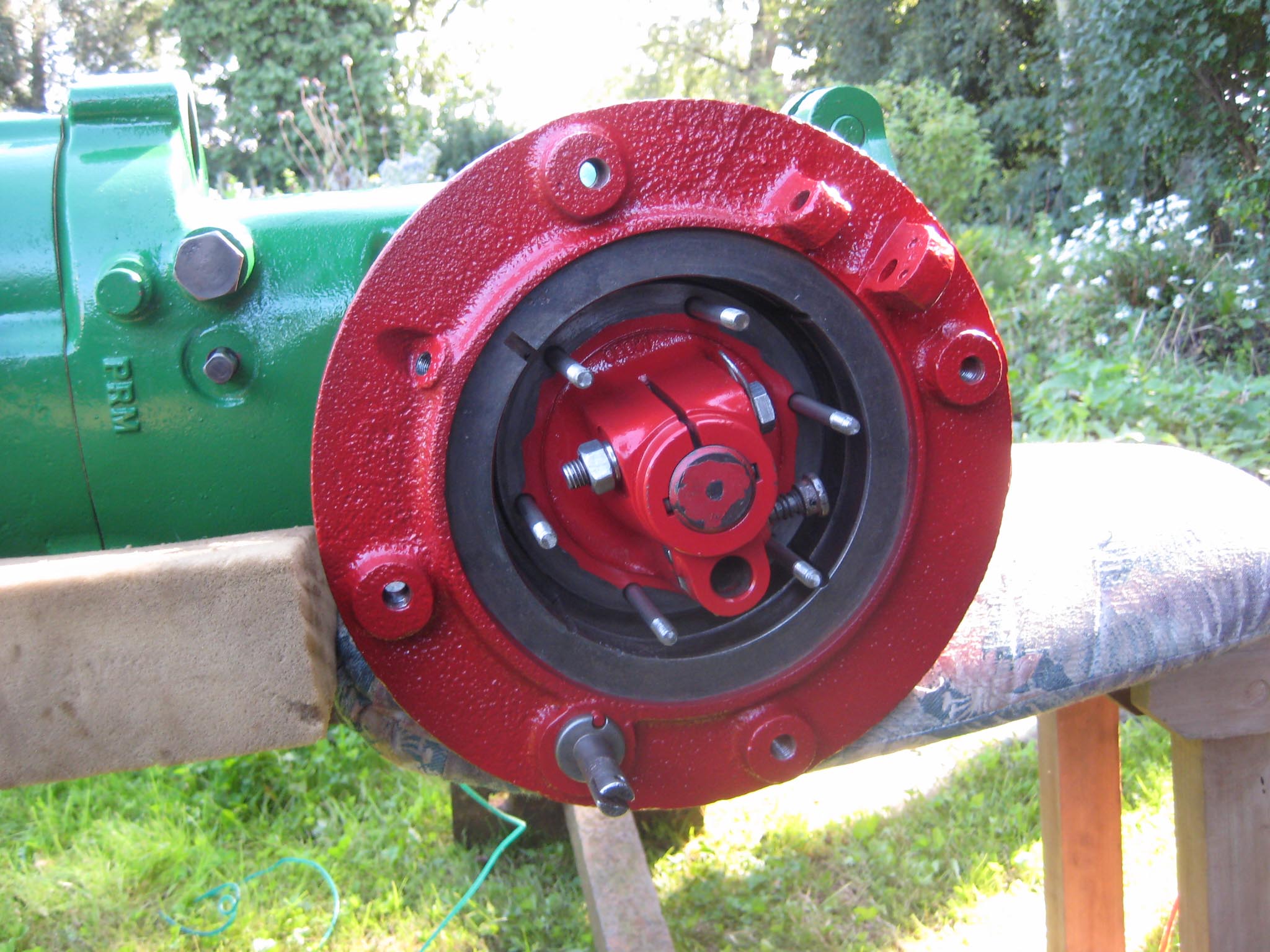
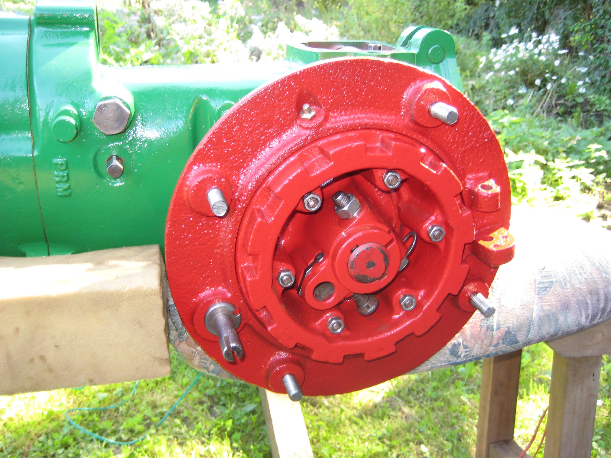
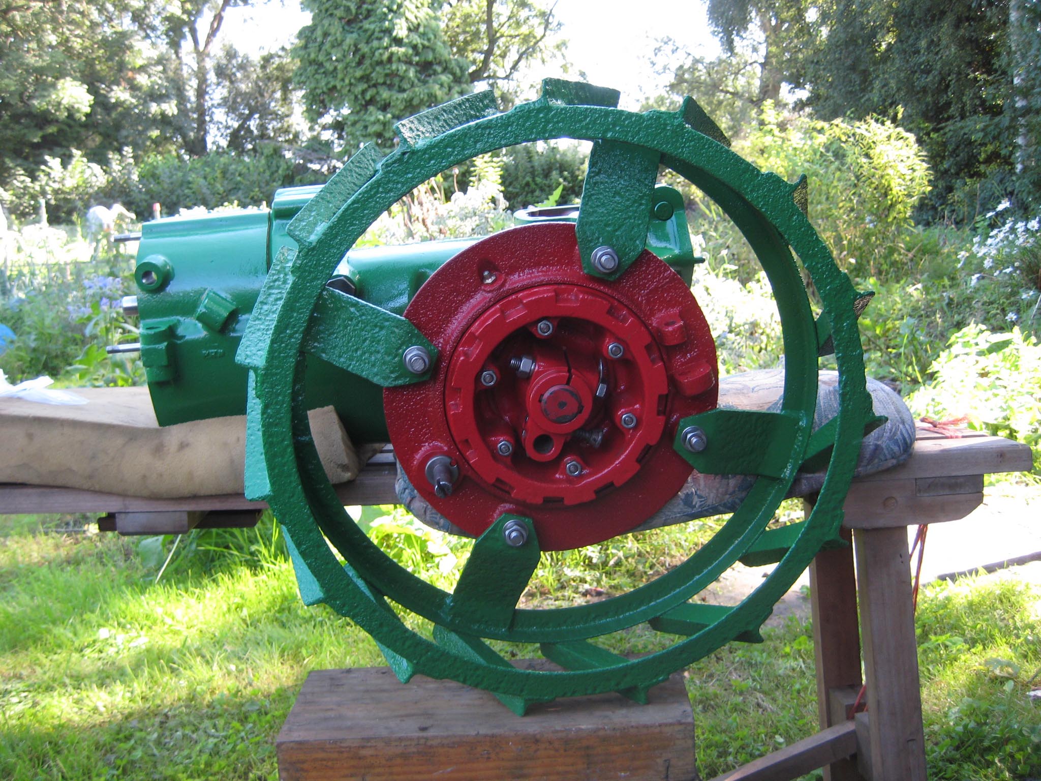
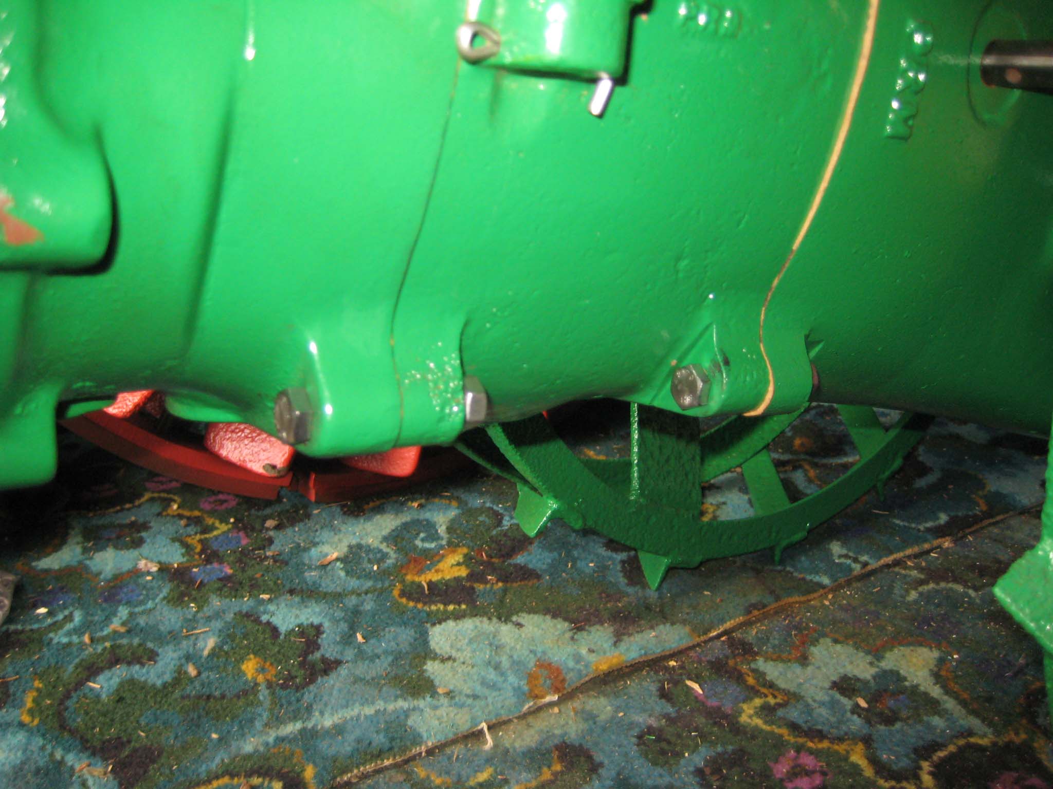
September 6, 2015 at 4:05 pm #14348vhgmcbuddyMemberI decided that I would next fit the wheels, simply to make the machine easier to move around, as it now needs at least two people to lift it. Six M8 threaded studs are screwed into the wheel flanges (Simar 0044). The pivot pin for the Red pawl was fitted to the road wheel discs. This locates onto a 6mm peg that prevents the pin from spinning around when you tighten up the M14 fine thread nut on the back (Simar 0045). The Red pawl and Green lock will be fitted at a later date. The wheel discs where slid into place over the bowl shaped extensions on the side of the gearbox (Simar 0046). The castellated casting fits onto the six studs. The four M12 studs which mount the wheels were then screwed into the wheel discs, along with a M10 x 1.0 grease nipple (Simar 0047). Final job for the day was to fit the wheels (Simar 0048).
Attachments:
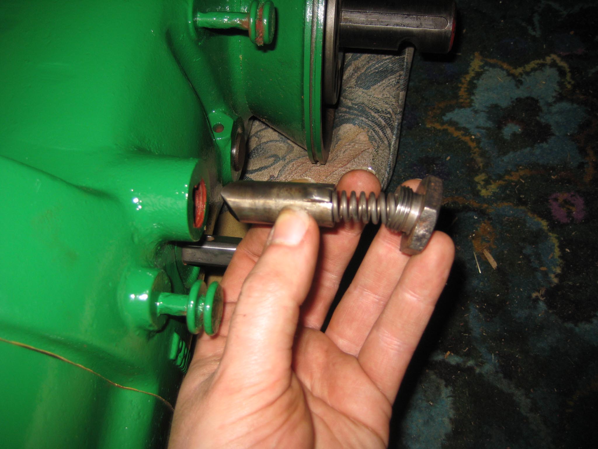
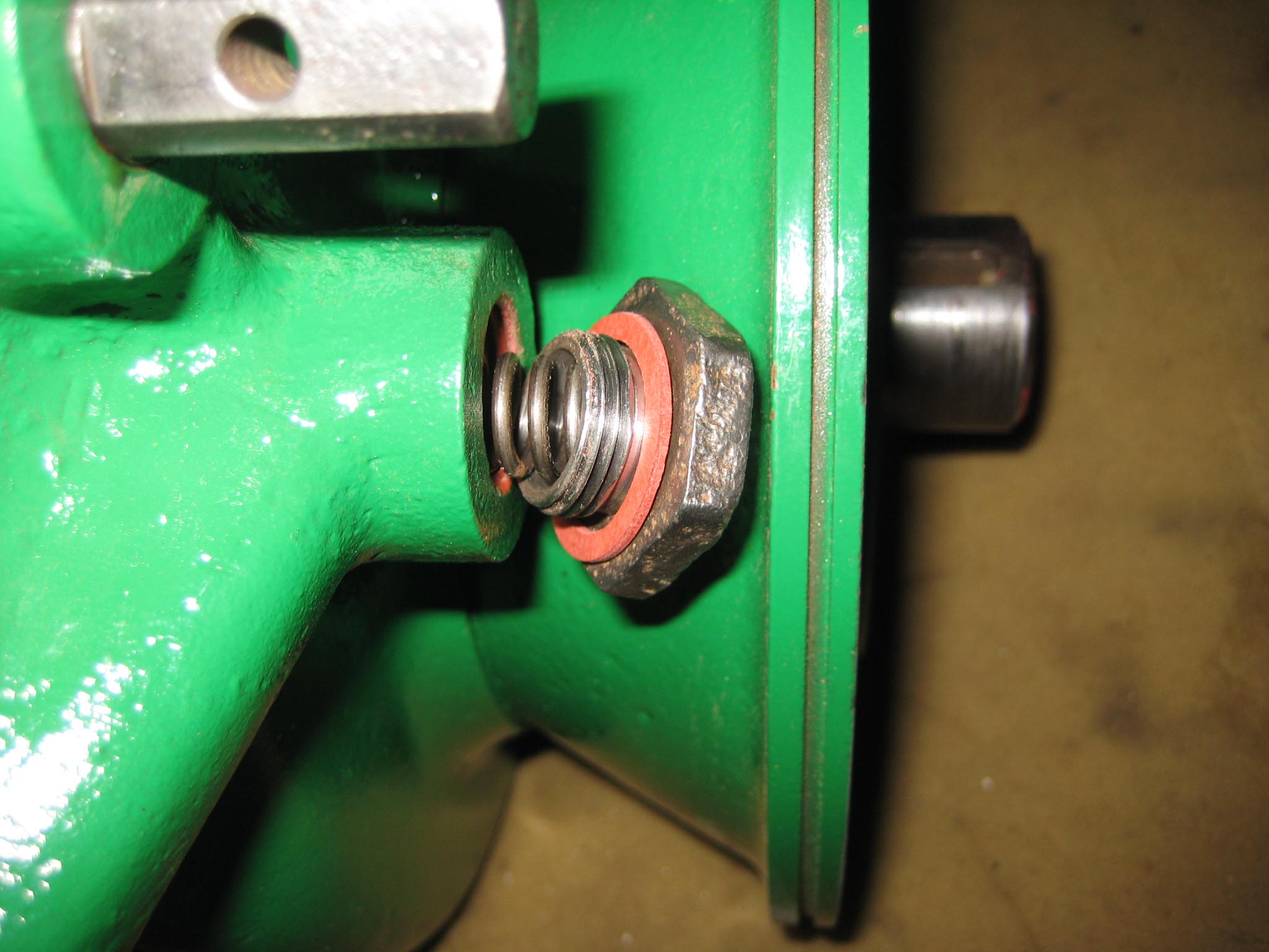
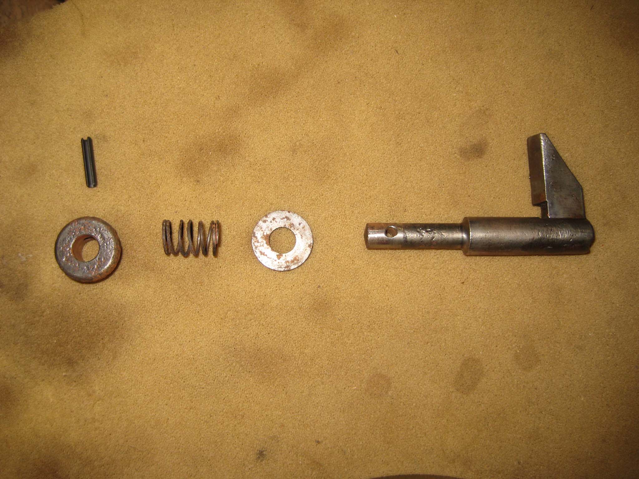
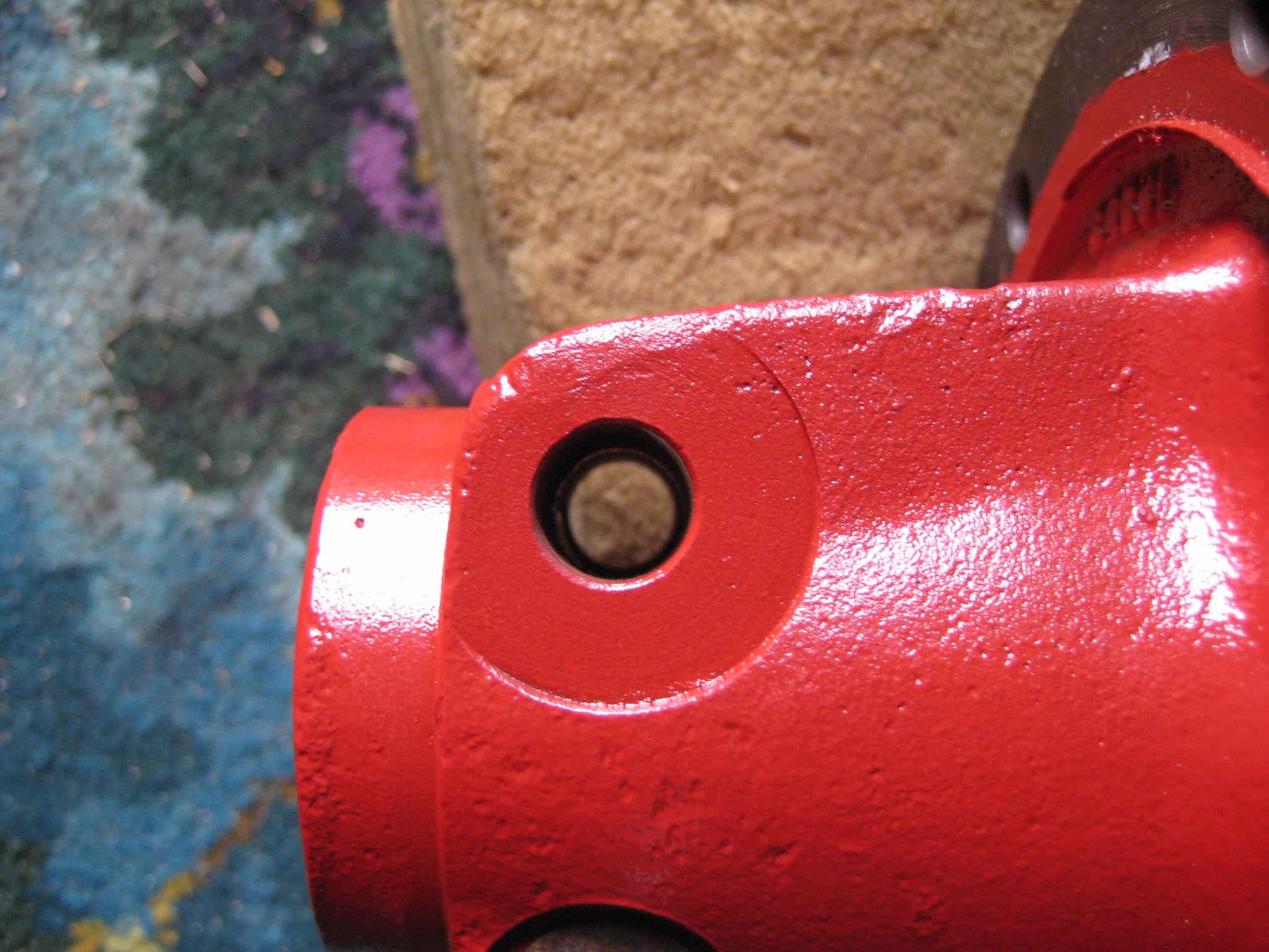
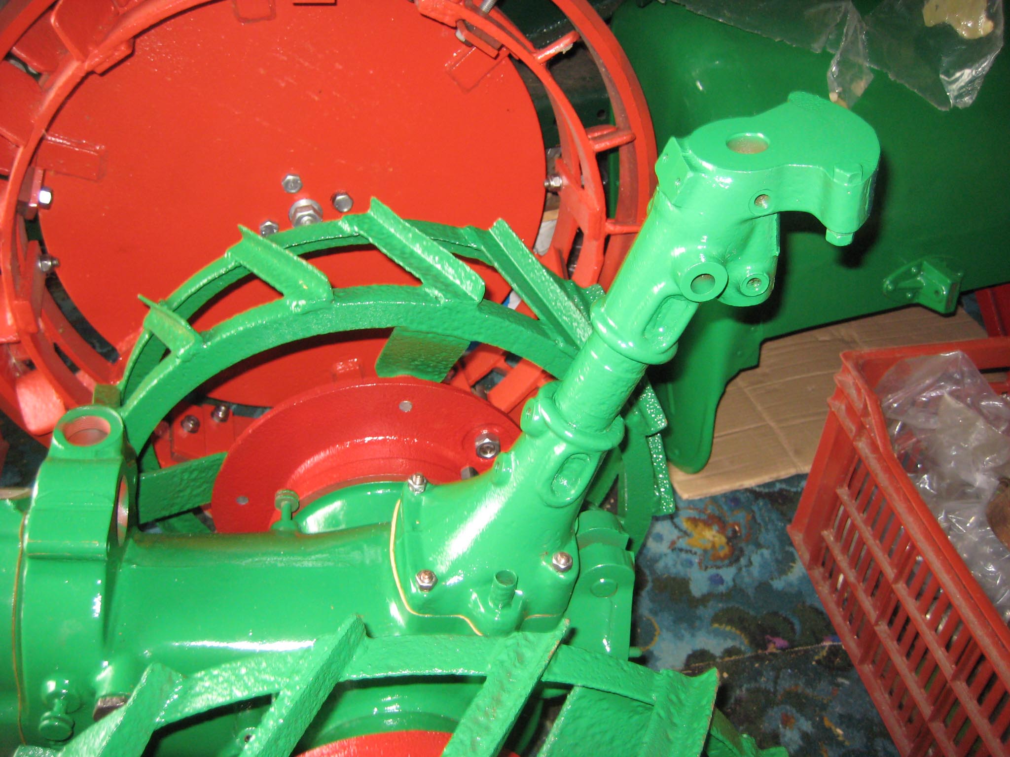
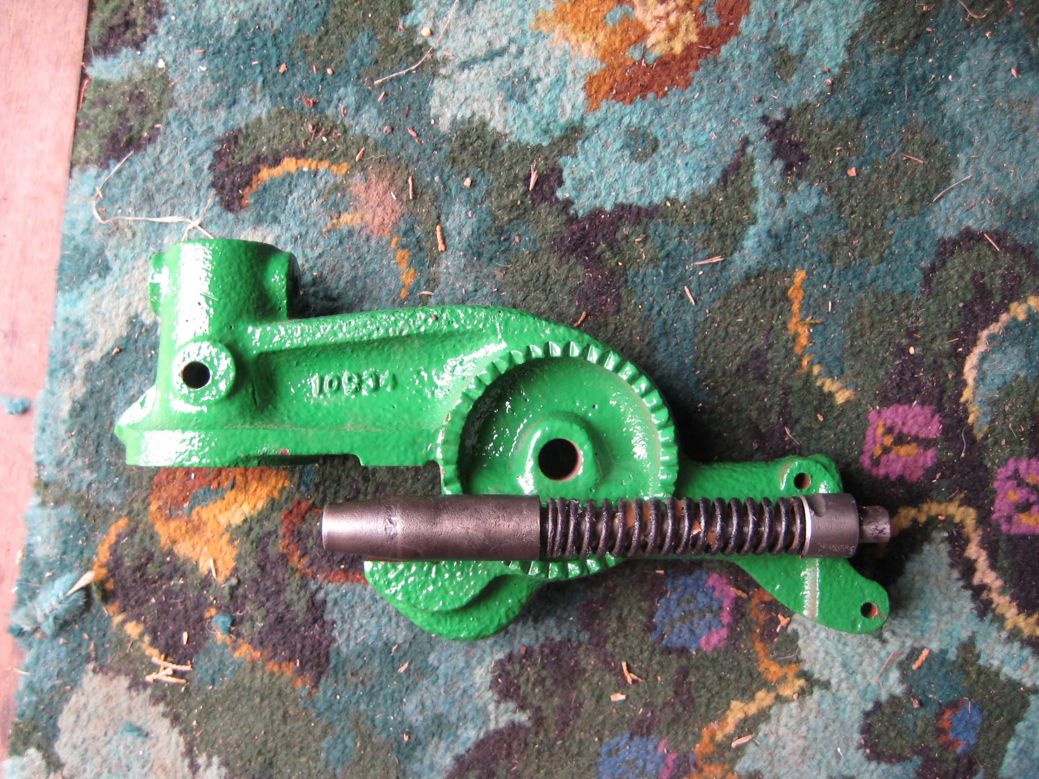
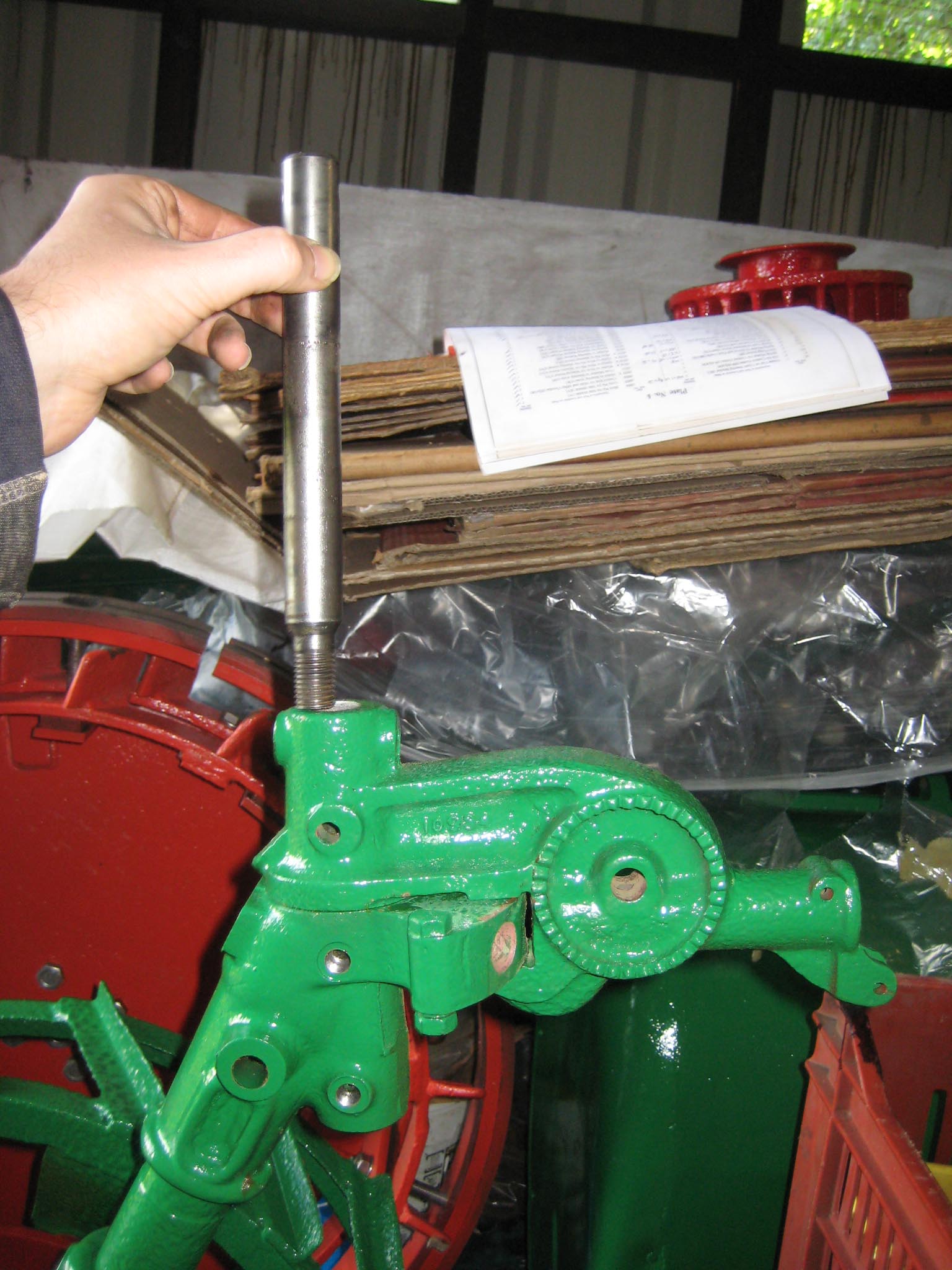
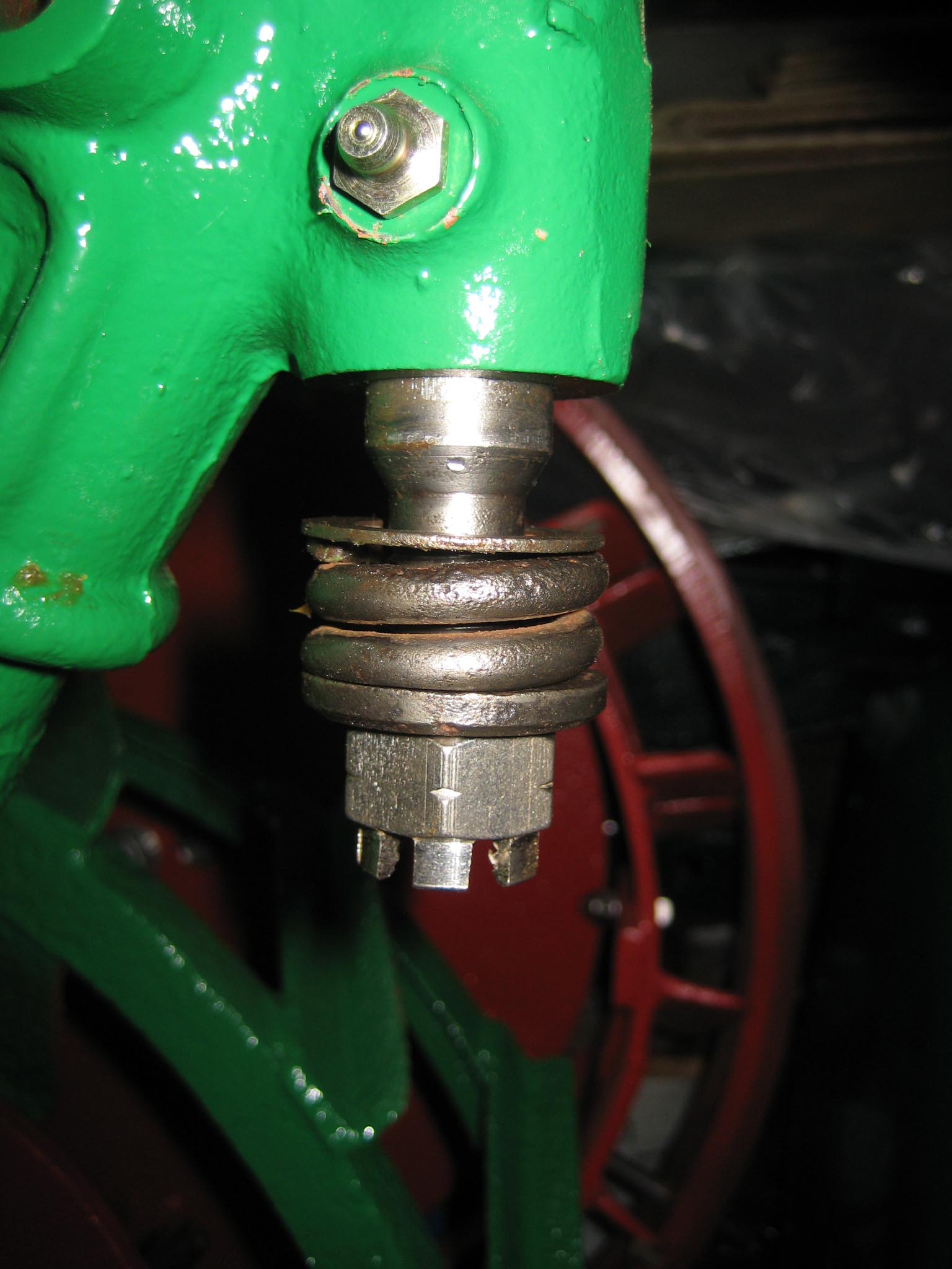
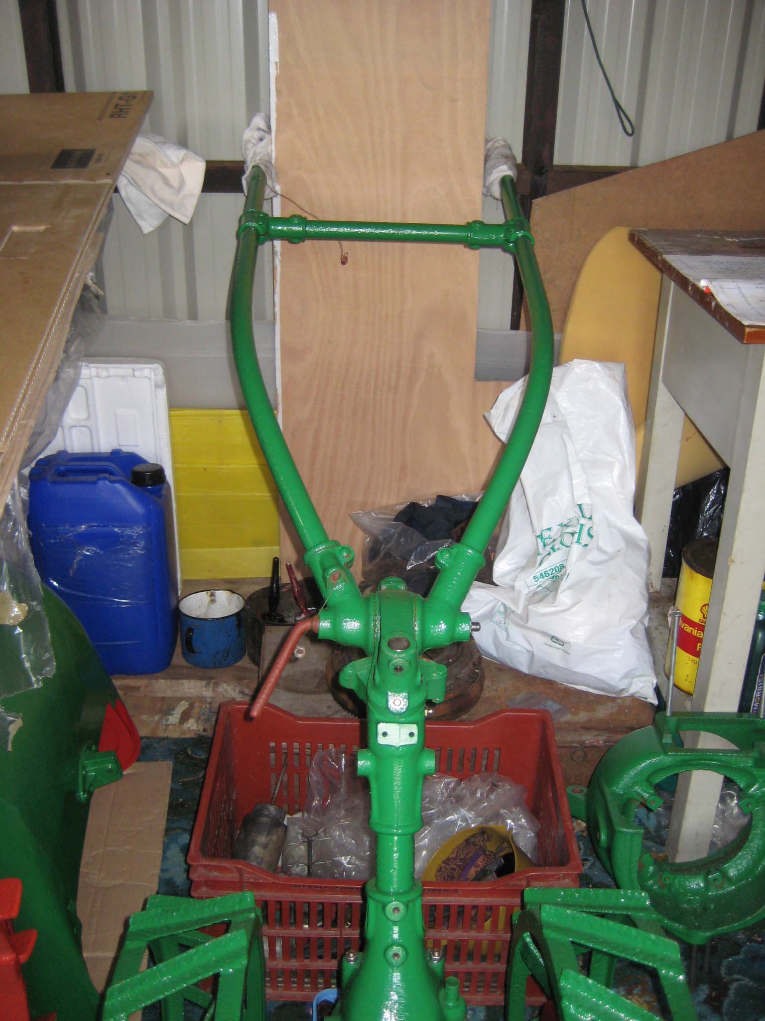
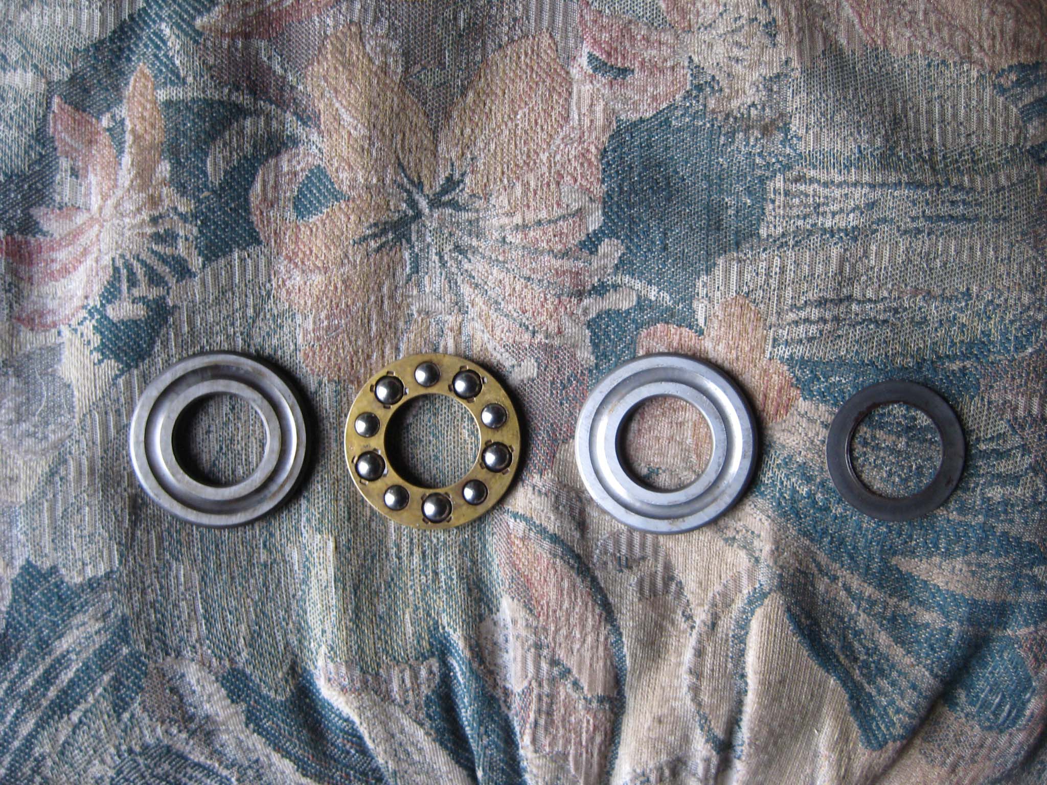
September 21, 2015 at 6:42 pm #14494vhgmcbuddyMemberBefore fitting the engine, I thought it would be best to have the handlebars back in place to make it easier to counterbalance the weight of the engine. The steering column assembly is attached to the rear of the main gearbox by four M8 studs, of which the two longer ones are fitted towards the rear. There is also a paper gasket between the gearbox and column (Simar 0049 & 50). Before fitting the swivel head for the handlebars to the steering column, the steering release plunger needs to be fitted (Simar 0051). Note the orientation of the collar to the right of the spring which includes a cut out for a 5 x 30mm roll pin. Slide the swivel head onto the top of the steering column, ensuring that the release plunger locates into one of the 3 tapered holes at the top of the column. With the swivel head in position, insert the pivot pin (Simar 0052). The pivot pin is locked into the swivel head using two 8 x 50mm roll pins. At the lowered end of the pivot pin, fit the washer, spring, collar, M16 castellated nut and 4 x 35mm split pin (Simar 0053). Note that the picture shows these items in the fully loosened position.
Attachments:
October 5, 2015 at 6:14 pm #14762vhgmcbuddyMemberThe handlebars are attached to the steering column via a locking handle and M12 nut (Simar 0054 & 55). Note that the M12 nut is larger across the flats than a normal plain M12 nut, as it fits into a hexagon recess at the handlebar pivot.
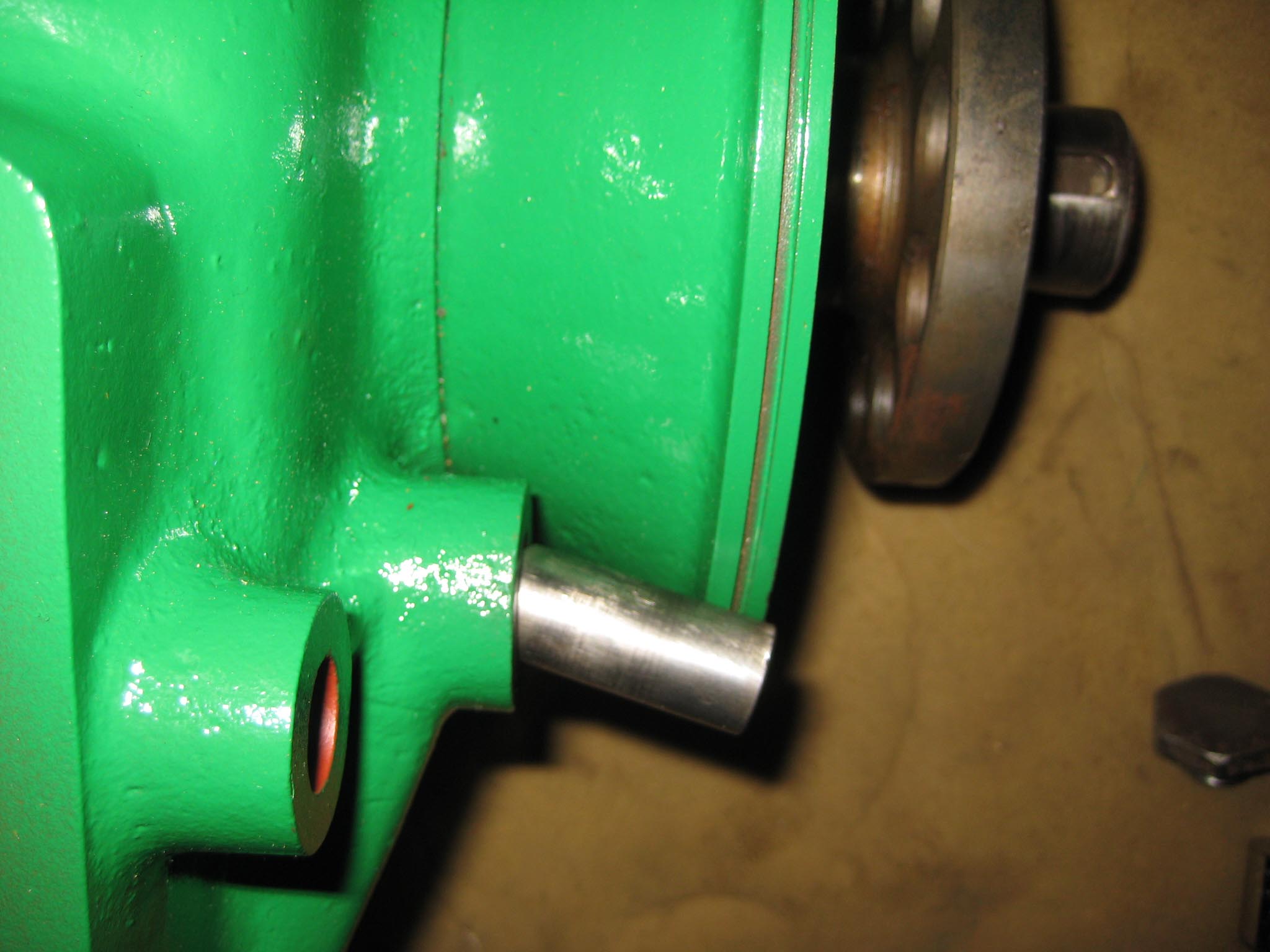
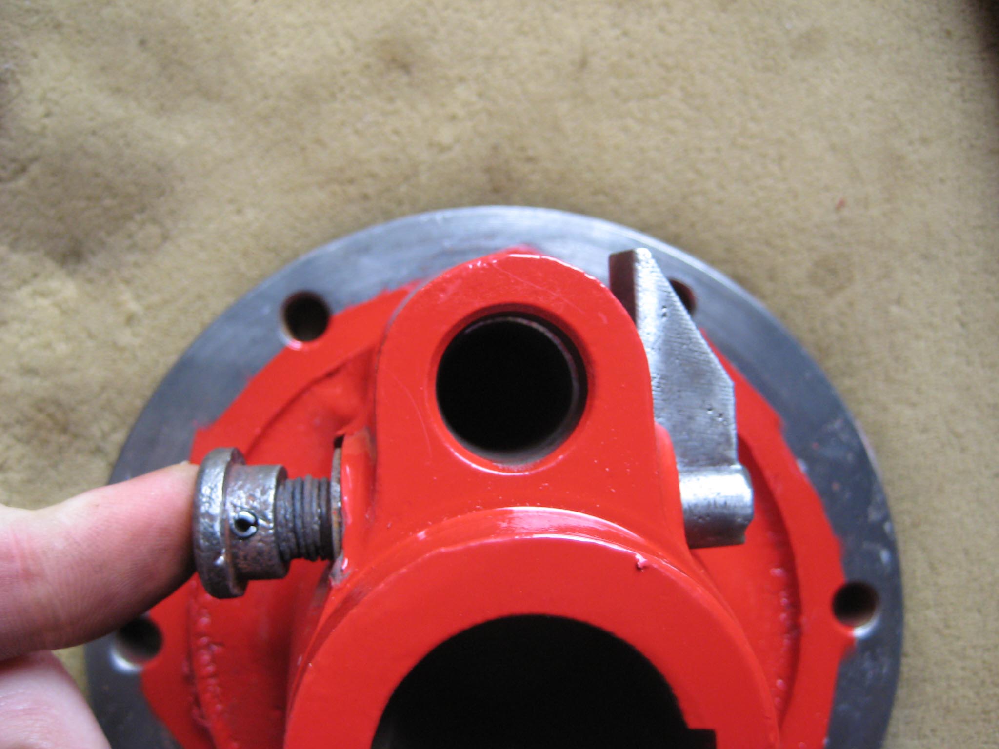
Before the engine could be fitted, there were a few items left to go in the reverse speed gearbox. The roller bearing for the end of the worm drive shaft went in first (Simar 0056), followed by the locking plunger for the reverse gear lever (Simar 0057). I did not fit the actual reverse gear lever at this stage, just in case I needed to manipulate the clutch when fitting the engine. To complete the worm drive shaft, a distance washer and thrust ring are fitted (Simar 0058), along with the clutch fork (Simar 0059). The clutch fork is held on the shaft via a washer and 4 x 20mm split pin (Simar 0060). When the legs of the split pin are bent over, they are very close to the reverse gearbox casing, so check the clutch operation a few times to make sure they don’t foul.Attachments:
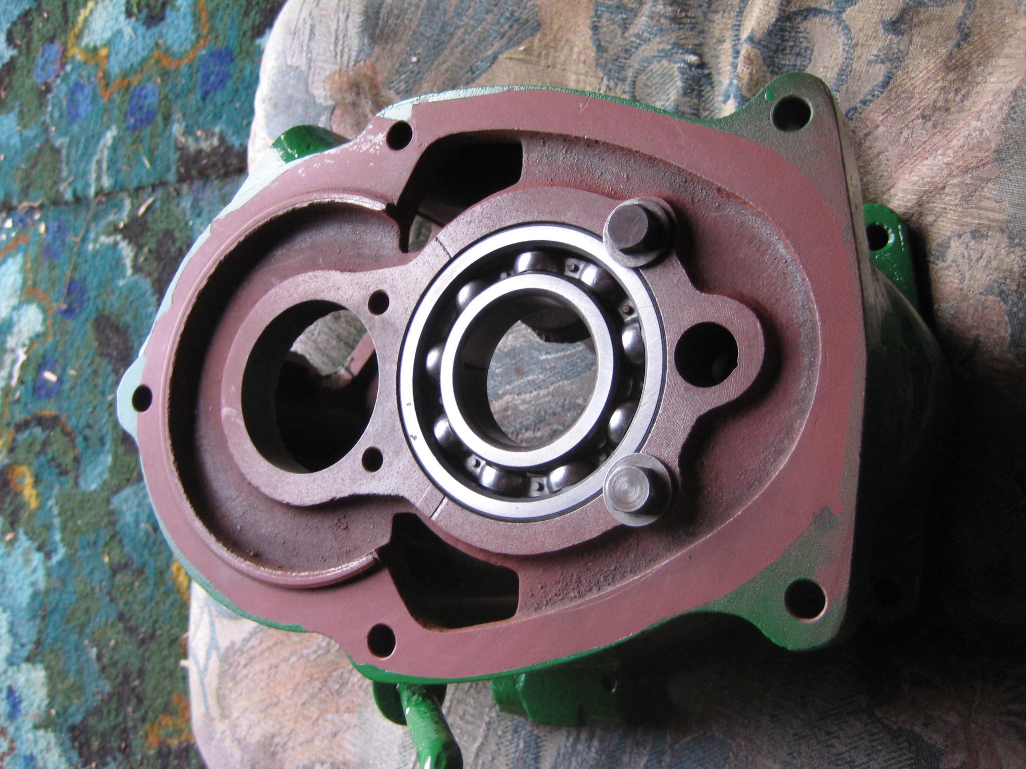
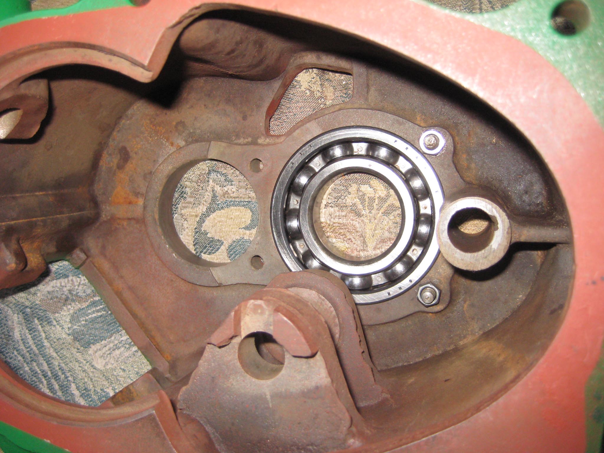
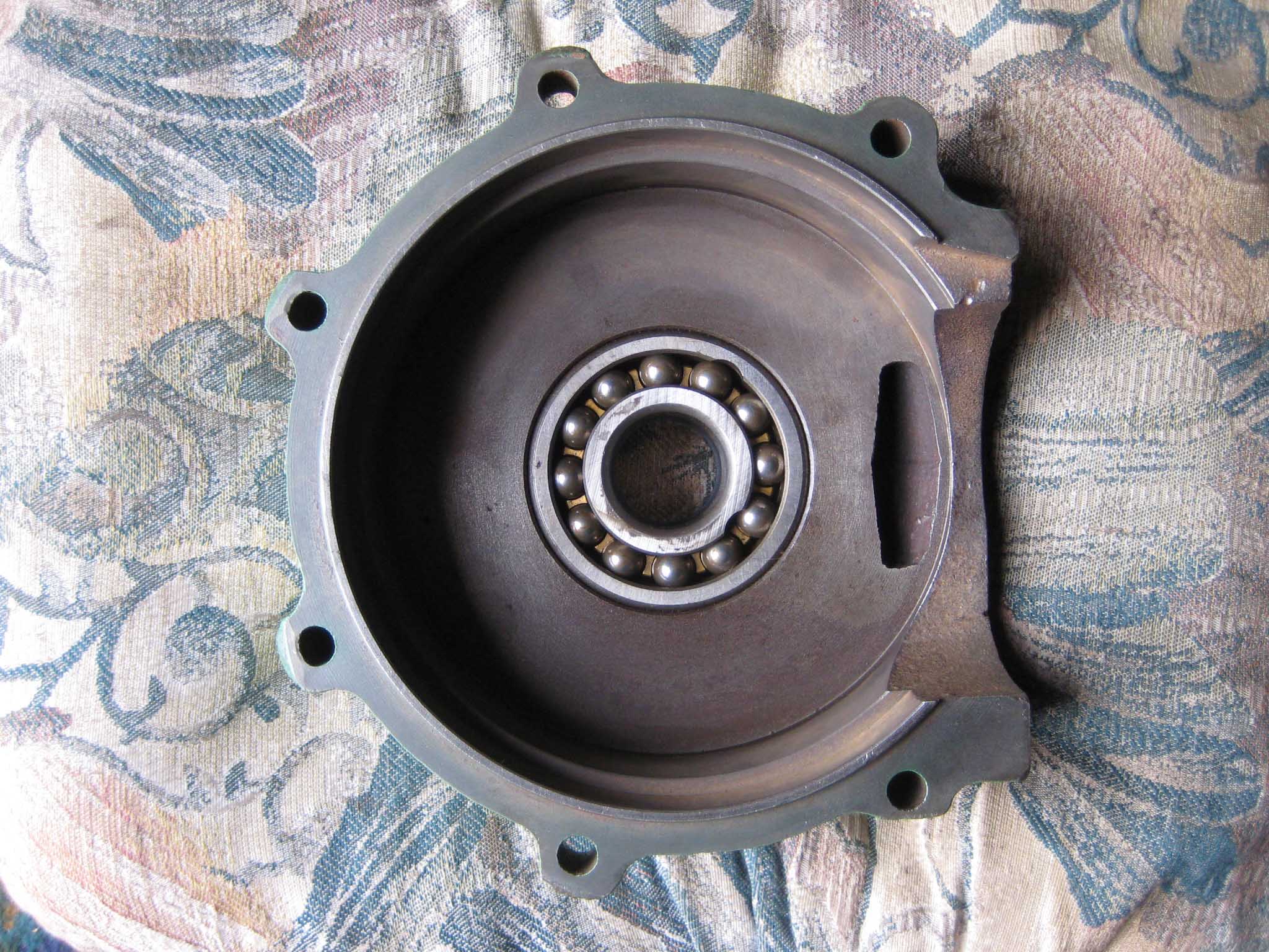
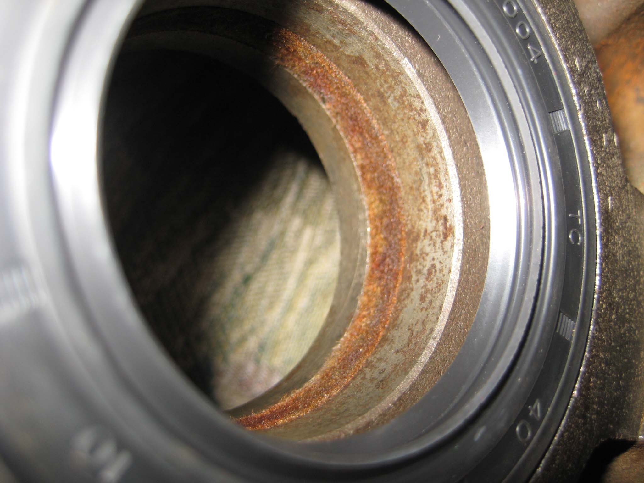
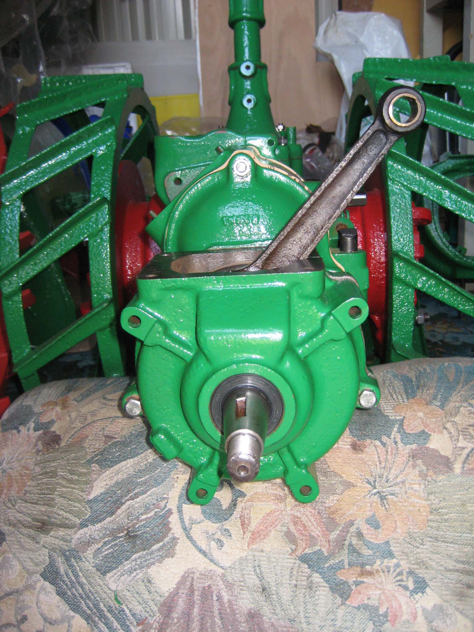
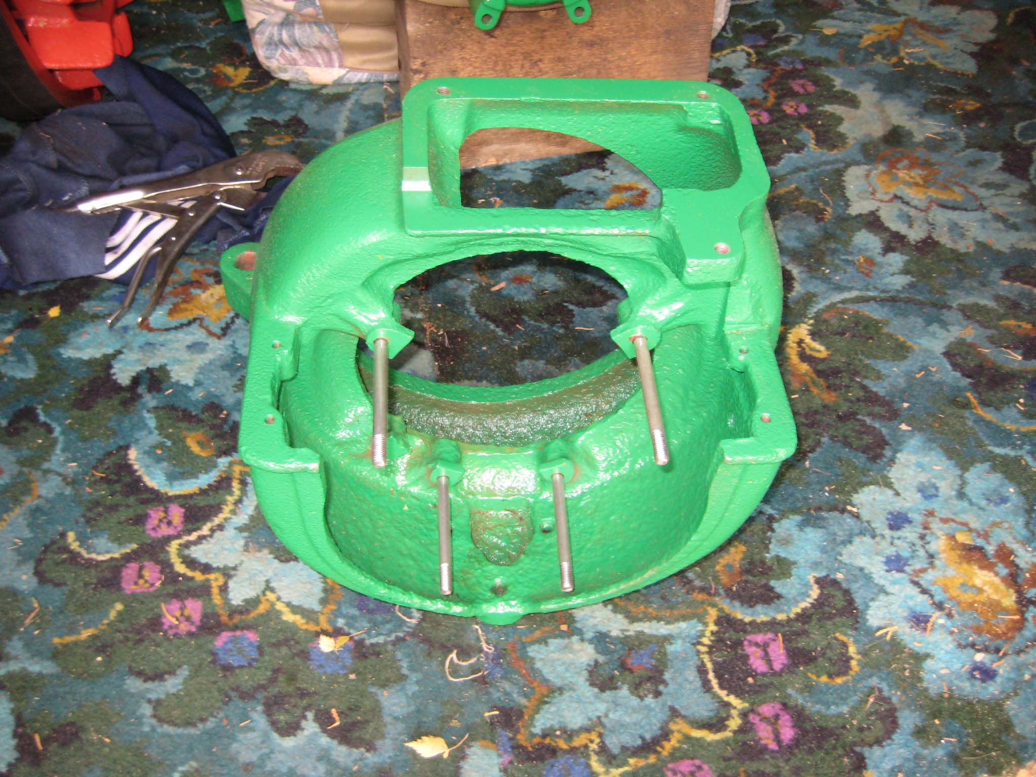
October 5, 2015 at 6:19 pm #14770vhgmcbuddyMemberThe crankcases were prepared for assembly by fitting new oil seals, 60mm O/D, 40mm I/D, 10mm wide for the rear crankcase and 47mm O/D, 30mm I/D, 10mm wide for the front crankcase (Simar 0061). The front crankcase also contains a double roller bearing (Simar 0062). As this bearing sits in a blind hole, it cannot be pressed out, so removal would require a special blind bearing removal tool which normally results in the bearing being damaged. As the bearing was in good order, I did not attempt to remove it. The rear crankcase contains a machined groove into which is inserted a felt washer (Simar 0063). A new paper gasket was fitted to the reverse gearbox casing (Simar 0064) and the rear crankcase secured into position on the three long M8 studs (Simar 0065). At the same time, the M8 x 50 bolts were fitted which secure the reverse gearbox to the main gearbox and rear crankcase to the reverse gearbox (Simar 0066). All were gradually tightened, in the same fashion as a cylinder head, to ensure an even pressure.
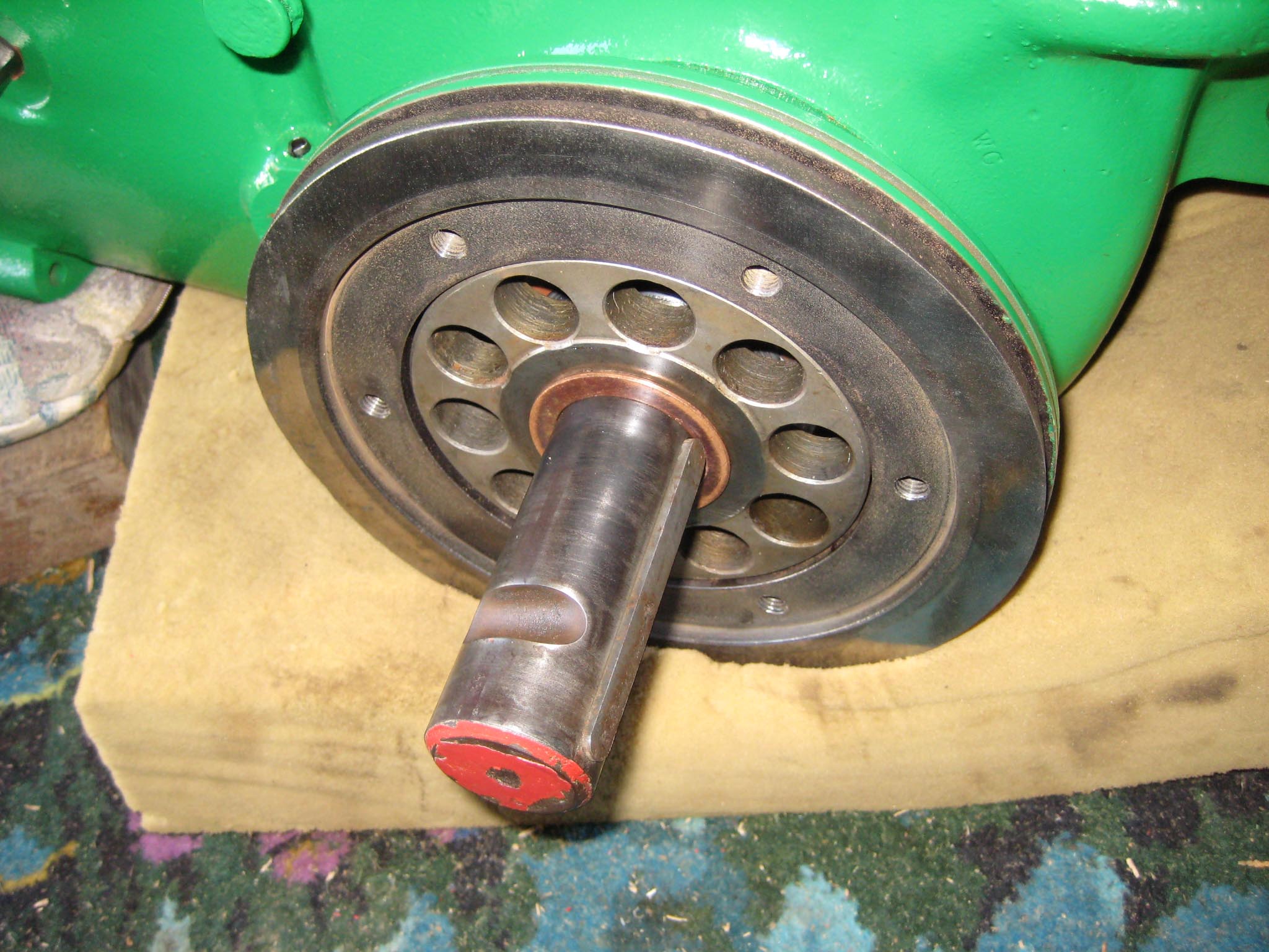
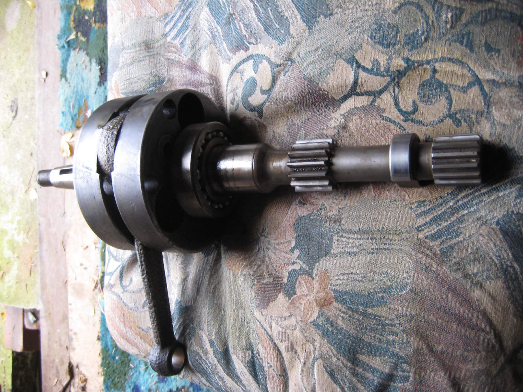
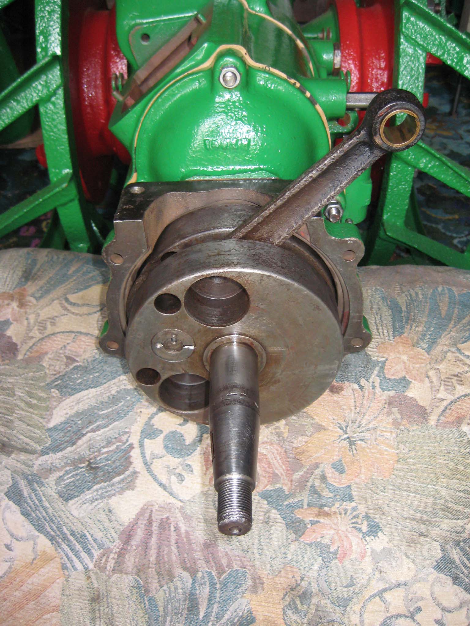
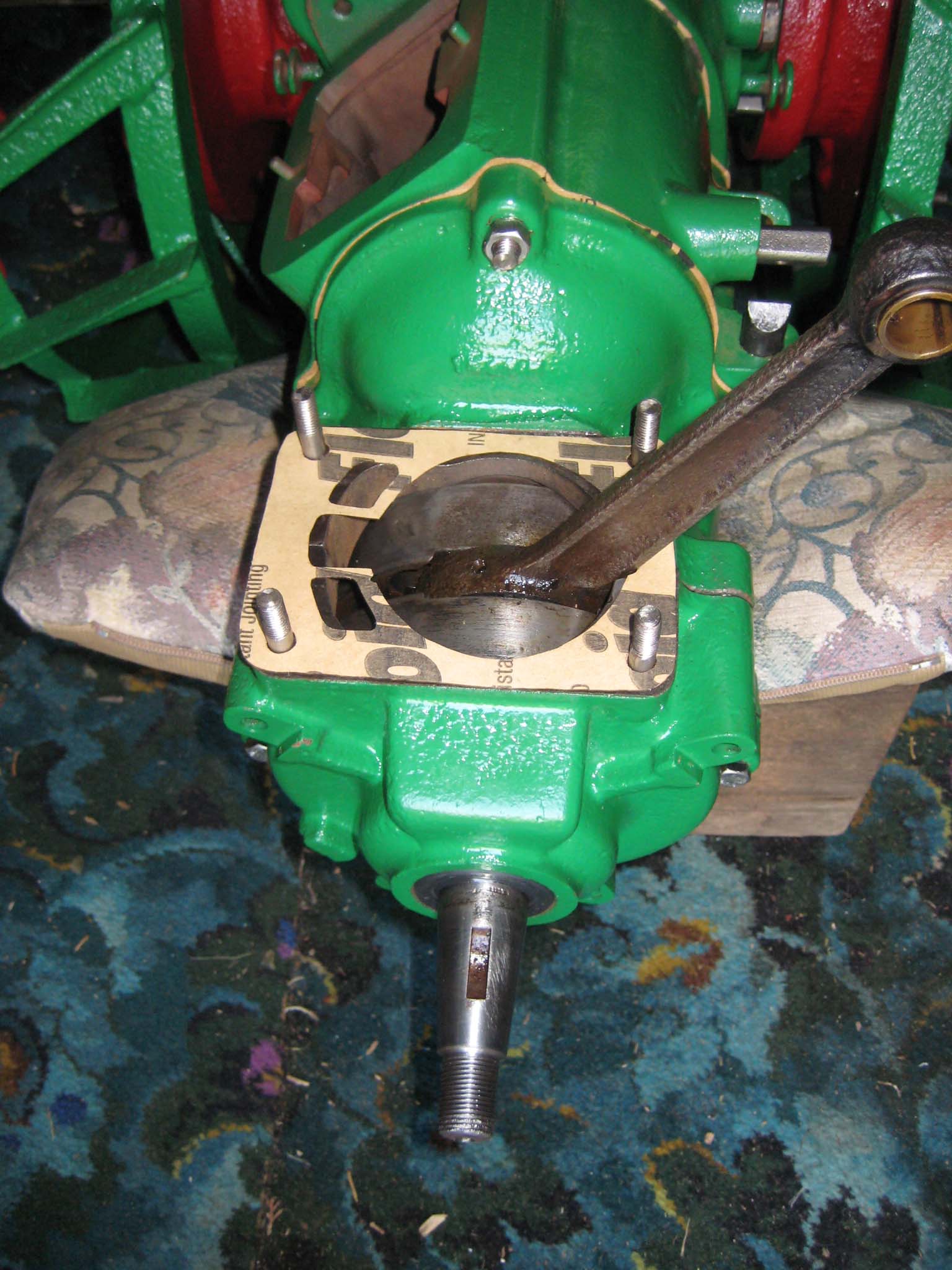
I did not take the engine crankshaft apart (Simar 0067), as reassembling would require a jig to ensure both front and rear sections of the crankshaft are perfectly concentric. The whole lot was slid into place, taking care not to damage the oil seal in the rear crankcase (Simar 0068). A distance washer is fitted up against the front flywheel before the front crankcase is installed (Simar 0069). The front crankcase is fixed to the rear crankcase by two M8 x 55 bolts. The other four vacant fixing holes visible in the photo also carry the front cooling fan casing. Four short M8 studs and paper gasket were then fitted ready for the cylinder barrel (Simar 0070).Attachments:
October 6, 2015 at 4:39 pm #14783charlieKeymasterOne method of removing bearings from blind holes is to fill centre of bearing with grease, then with a bar of suitable diameter (slightly less than centre of bearing) placed in this hole a sharp blow with a hammer should do the trick. This is the method for removing rear layshaft bearing in series Land Rover gearboxes.
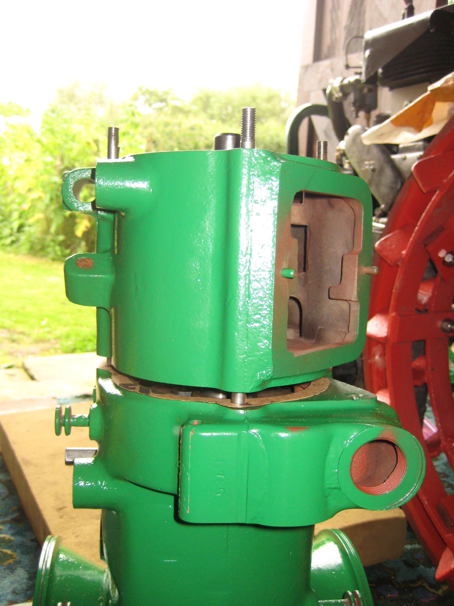
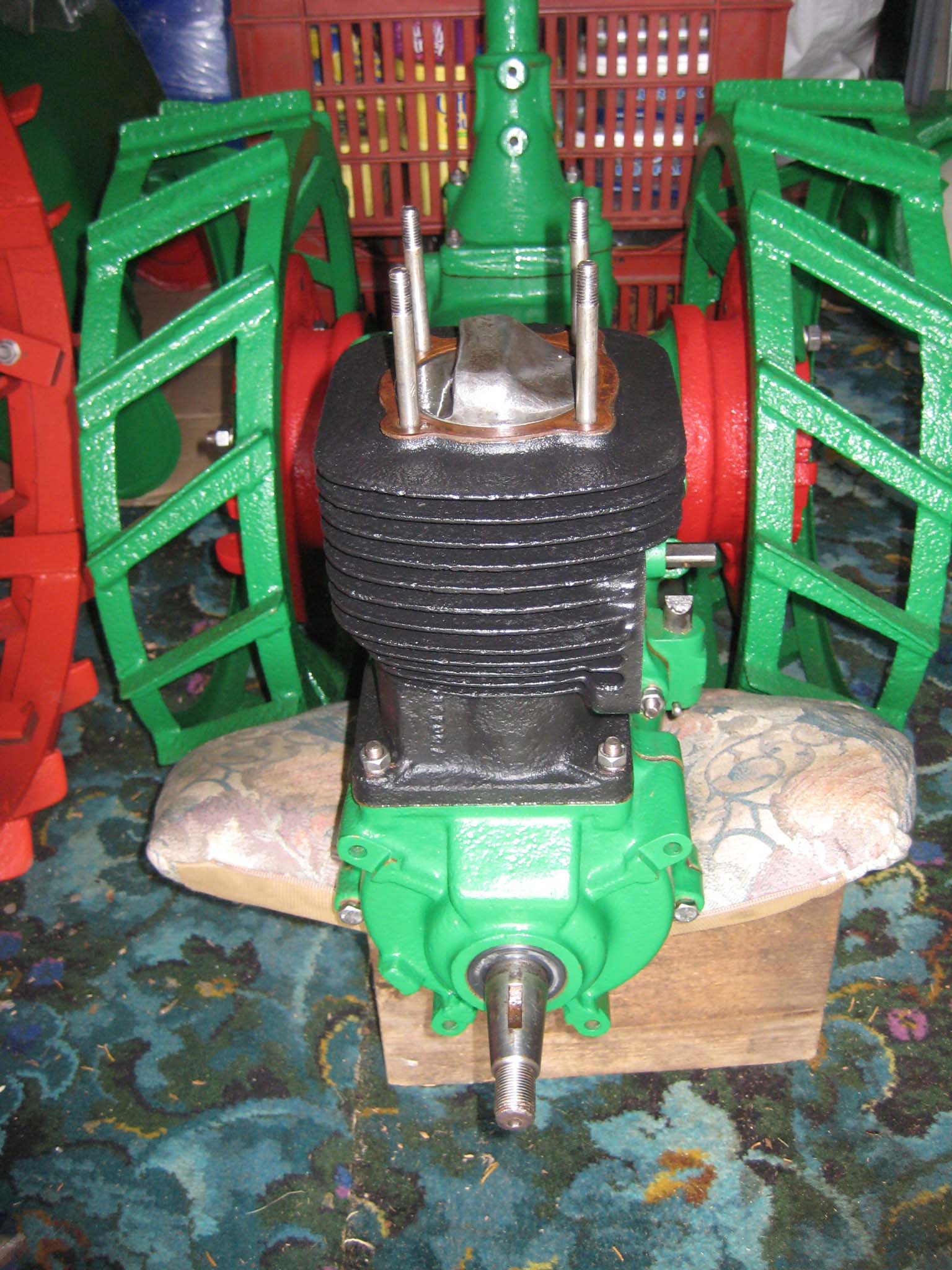
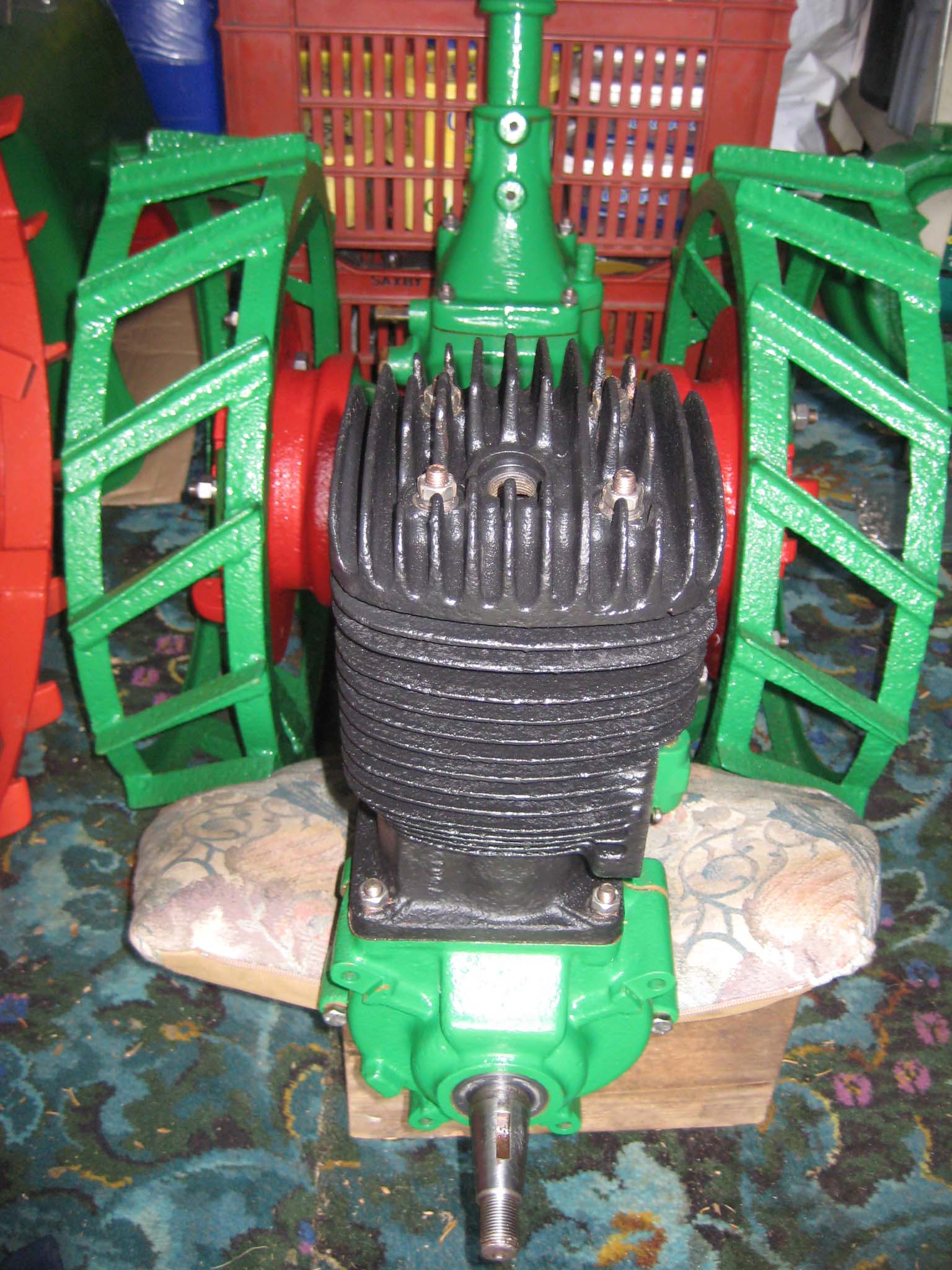
October 7, 2015 at 5:08 pm #14787vhgmcbuddyMemberAfter refitting the piston, the cylinder barrel, cylinder head studs and head gasket were installed (Simar 0071). Note the orientation of the piston. The cylinder head needs to be aligned so the spark plug hole is towards the front (Simar 0072).
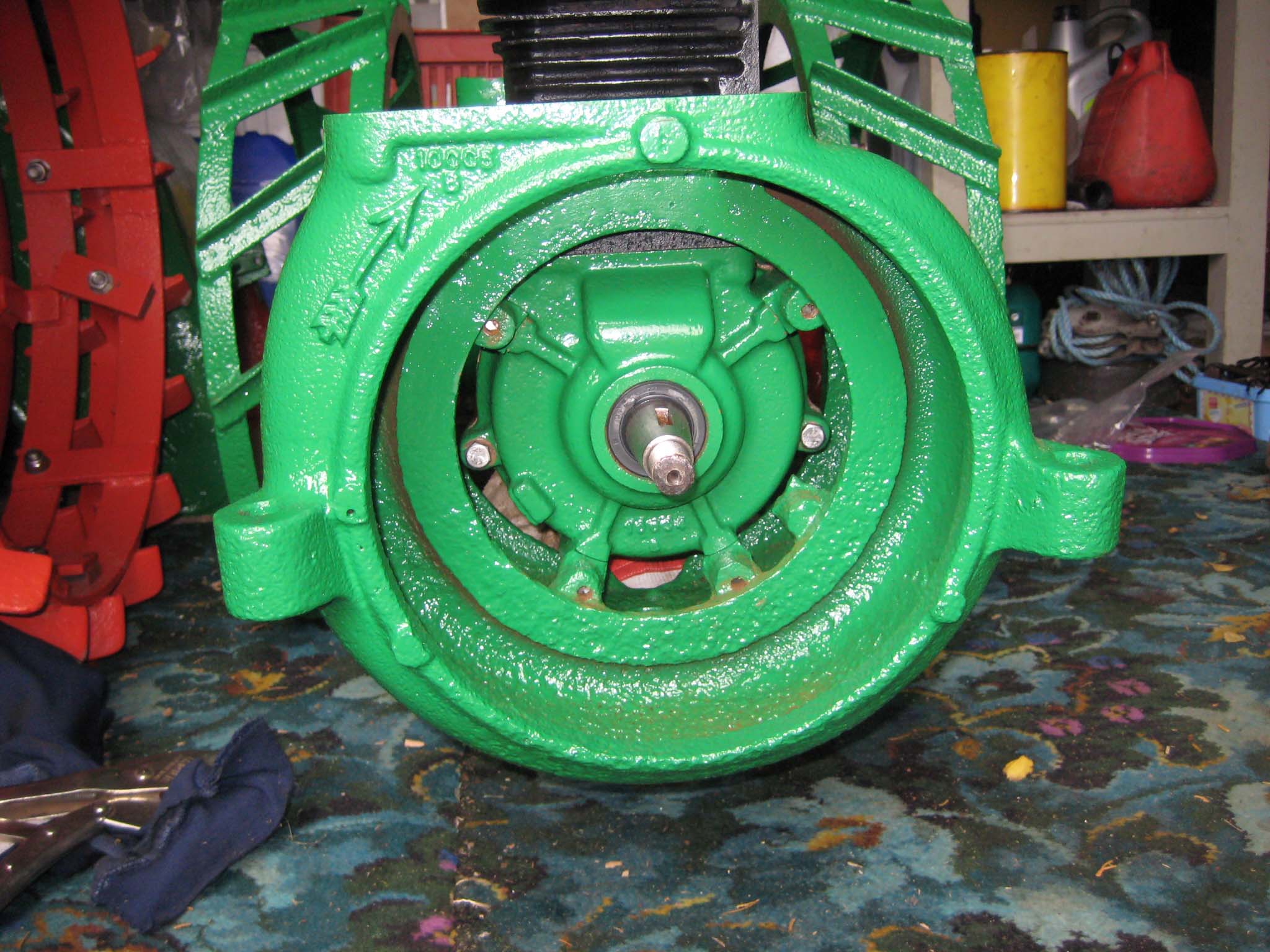
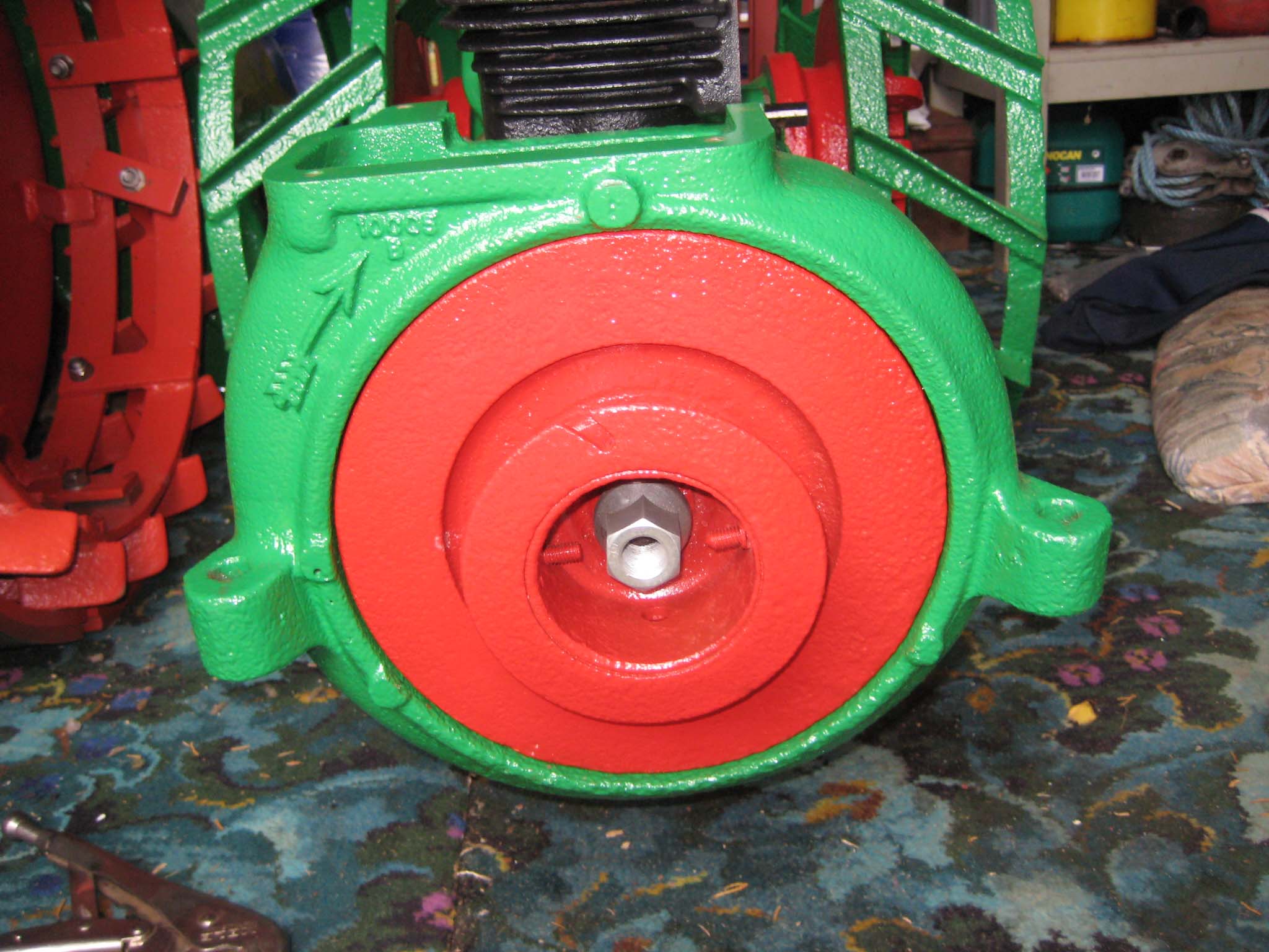
The cooling fan casing was prepared by installing the four M8 mounting studs (Simar 0073) and then fitted to the crankcase (Simar 0074). The cooling fan fits on the tapered crankshaft via a half moon key. A M18 x 1.5 nut holds the fan in place. The original nut was too corroded for reuse, so a replacement was obtained in the form of a wheel nut from a piece of agricultural machinery (Simar 0075). This also had the advantage of being a flanged nut, therefore I did not require the large washer which was used with the original nut. Note that in the photo the nut has yet to be tightened. The cylinder was filled with a cloth rag to lock the piston in place to allow the nut to be tightened.Attachments:
-
AuthorPosts

- You must be logged in to reply to this topic.